Continue to Site

Welcome to our site!

Electro Tech is an online community (with over 170,000 members) who enjoy talking about and building electronic circuits, projects and gadgets. To participate you need to register. Registration is free. Click here to register now.

  • Welcome to our site! Electro Tech is an online community (with over 170,000 members) who enjoy talking about and building electronic circuits, projects and gadgets. To participate you need to register. Registration is free. Click here to register now.

Advice Sought on DIY Leads for HP Frequency Counter

Status
Not open for further replies.

Blackgate

New Member
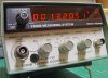
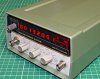
Hi all. I've just purchased a vintage HP 5300B Measuring System with the HP 5305B 1300MHz Frequency Counter module.

As an electronics hobbyist, I'm planning to use this baby to to help me test and repair my vintage HI-FI amplifiers and receivers from the 1970's. Classics!

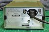
The HP Frequency Counter has two BNC connectors on the front for frequency counts up to 1300MHz, plus a BNC connector at rear to connect to an oscilloscope. The unit did not include any leads when I bought it and so I'm hoping that some bright spark here can clarify and confirm some questions for me in the interest of accurate measurement.

1. Are oscilloscope probe leads suitable for use with this unit?

2. If I make a DIY set of leads for measuring (and/or to connect to an oscilloscope), is it 'correct' to use 50 Ohm cable, and will it matter if the inner core of the cable is stranded or solid?

Lastly, I do not know when this Frequency Counter was last calibrated. As a guide, how regularly should it be serviced for novice use? I assume these units have been well built and are quite stable, yes?

Many thanks.
 

Attachments

  • c928410b.jpg
    c928410b.jpg
    91.3 KB · Views: 810
  • 54090ac0.jpg
    54090ac0.jpg
    150.7 KB · Views: 701
  • 7bec06c1.jpg
    7bec06c1.jpg
    192.7 KB · Views: 432
Last edited:
I would have thought scope leads would be fine, and to link to a scope, a standard 50 ohm BNC lead.

However, I fail to see what help a frequency counter will be for your particular task?.
 
1. Are oscilloscope probe leads suitable for use with this unit?
The "B" input* has a 1 Mohm impedance and so a 'scope probe would be ideal to use here.
The "A" input* is 50ohm impedance. You could use a 1:1 probe, but a ÷10 probe would give a very high
attenuation. As long as the counter has enough input to count reliably, it does not matter.
I sometimes use a scope proble on my counter or spectrum analyser, when looking for a frequency, but if I want to make a measurement of voltage on the analyser, I use a coax cable.

* Another edit, I originally assumed that the A input was the low frequency high impedance input, but no, it is B on this counter.
My counter, a Racal, has the A input as the LF input.
Dont you just hate it when this sort of thing happens:mad:

2. If I make a DIY set of leads for measuring (and/or to connect to an oscilloscope), is it 'correct' to use 50 Ohm cable, and will it matter if the inner core of the cable is stranded or solid?
50ohm coax will do just fine, solid or stranded is OK.
However, you may find the coax a bit stiff, if you can find some thin flexible coax you will find it easier to use.
I have a few cables "BNC to Crocs" which I use for general test situations, I think they started life a BNC to BNC in some computer/communication/what have you system, nice flexible coax about 3mm diameter. I cut them up and fitted croc clips on the cut end, and was pleased with the result.

Lastly, I do not know when this Frequency Counter was last calibrated. As a guide, how regularly should it be serviced for novice use? I assume these units have been well built and are quite stable, yes?

For your application I dont think you need to worry about calibration.
HP equipment was very well made, if it works it is 99.9% sure to be OK.

JimB

Editing:
plus a BNC connector at rear to connect to an oscilloscope.
Just having had a look at the photo of the rear of the counter, the OSC connector is not for connection to an oscilloscope.
It is almost certainly an output from the frequency standard oscillator within the counter.
 
Last edited:
The A input is 50Ω, so a 10X scope probe will not work there. The B input is nominally 1megΩ, so a 10X probe would work there.

On the A input, get a 5' piece of RG58 with a BNC at one end and two mini insulated clip leads at the business end. Separate about 2" of the shield and center conductor, insulate the shield with heat-shrink, and attach the clips to the resulting pig-tails.
 
Last edited:
1. You can use oscilloscope probes if the counter inputs are 1MΩ (but will give a 10:1 reduction in sensitivity). If they are 50Ω, then you can't. You can measure the inputs with an ohmmeter if you don't know what they are.

2. 50Ω coaxial cable is the correct cable for the connection. Stranded will be more flexible that solid, so it's often preferred for test leads.

It's unlikely that it will ever need calibration for your purposes. The counters are gernerally very stable, with an accurate crystal oscillator time base.
 
Don't forget that you have to consider the input capacitance of the counter (vs. a scope) when using an attenuator probe. An improperly compensated probe will kill upper-frequency signals. Many scope probes will not compensate for over 30pF in input capacitance (20pF is pretty much the norm for the input capacitance of scopes).

An X1 probe is not just a piece of wire. Some of the best X1 probes have a bandwidth of 11MHz. Input capacitance is the killer load for X1 probes. The center conductor of a decent X1 probe is actually resistance wire that may measure a couple hundred ohms or so. That makes them poor choices for use on 50 ohm inputs when working with low-impedance circuits as they will act as voltage dividers. For the same reason, using an X1 probe on the output of a function generator to deliver a signal to a low-impedance circuit is a poor choice.

To properly check probe compensation on a counter, you're going to have to get in to the counter circuitry with a scope where the scope won't affect input conditions and before the signal is diddled with (limited, squared, whatever).

Dean
 
Status
Not open for further replies.

Latest threads

New Articles From Microcontroller Tips

Back
Top