Continue to Site

Welcome to our site!

Electro Tech is an online community (with over 170,000 members) who enjoy talking about and building electronic circuits, projects and gadgets. To participate you need to register. Registration is free. Click here to register now.

  • Welcome to our site! Electro Tech is an online community (with over 170,000 members) who enjoy talking about and building electronic circuits, projects and gadgets. To participate you need to register. Registration is free. Click here to register now.

Advice regarding the upgrading of a circuit board

Status
Not open for further replies.

LesM

New Member
Hi all
I am in need of some advice regarding a circuit I have.
The working of this circuit is just what I require except that it cannot Handel the amps that the motors (2) draw.
The project is to replace the door mirrors on my mini with folding mirrors, the 12v motors have 2 wires to operate them when the connections are reversed the motor runs in the opposite direction, I am not sure if at the end of there movement the power is cut by the mirrors them selves so to prevent any possible damage to the motors the circuit board has timers that cut power after an adjustable length of time
I have checked the amps that is drawn on 1 motor vehicles in the opening direction and in the closing direction, opening = 3.7 amps to fold out and 2.7 amps to close fold in
At the end of the travel when motor has stoped there is 0.13mA showing on the meter, would this be considered safe or would having the timed cutoff be best things.

Apart from the relay can anyone advise me regarding any other components that should be changed.

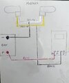
Below is the information for the circuit board
And a picture showing the components used

Cyclic Time relay with separate adjustable two timers.
Timer 1 - 1 to 700 sec
Timer 2 - 1 to 300 sec
With reversing the polarity at every cycle
Power supply - 12V DC
Output - 12V DC 2A
DPDT Relay: 2А/12V DC. Up to 24 w motor
Times are adjusted by two adjusters
D498DD78-434B-4056-9415-CC18C4762F13.jpeg
 
If you connect 12 V to the motor and the current drops to 0.13 mA, you can safely assume that you can leave that on all the time.

Have you looked at the circuit diagram of a car that already has the folding mirrors? If the left and right mirrors are in parallel, there has to be something to limit the power to whichever mirror gets to it's end of travel first. Once a device to do that has been designed, the manufacturers are likely to have used something that can limit the current for continually, and the reading of 1.3 mA seems to say that they have done that.

The timer relay you have shown appears to be one that cycles on and off. You want something different. You want a timer that runs briefly for one direction in response to an input, and then does nothing until the opposite direction is selected, when it should run in the other direction for a short time.

I think that you want two one-shot timers. Something like this:-https://www.ebay.co.uk/itm/314160572814

You would need to connect +12 V to NO (normally open) on both timers, ground to NC (normally closed) on both timers. Put the door mirrors in parallel and connect them between the Common terminal on one time and the Common terminal on the other timer.

Connect +12 V to Vcc and ground to Gnd on both timers.

Two pushbutton switches, one for fold in and on for fold out, would go to the trigger inputs of the two timers.
 
Driver300
Thanks for taking the time to respond to my inquiry, I have looked at the circuit on eBay, if I used the 2 boards setup as
you have suggested would it be possible to use a remote fob to operate the open and close triggers, something like
https://www.ebay.co.uk/itm/263962395762.
Or have you a better suggestion, either way any advice on how to setup a working system would be appreciated.
I look forward to any advice you may have.
Les
 
That radio receiver has only one output that turns on with one button and turns off with another. It doesn't say if it uses more current when turned on. If it does use much more than 4.5 mA you should only power it when the car is on.

I don't know if you want to use the timers. If I was sure that the mirrors only took 1.3 mA when they got to end of travel, I would leave them powered and not bother with timers.

A single output device like that radio receiver could be used quite easily without the timers, but would be more difficult with the timers. I would look for a radio receiver with two momentary outputs if you want to use the timers.

If you use that radio receiver without timers, you could wire it with two normal 5 pin automotive relays as follows:-

+ve power from an ignition feed to the red wire of the radio receiver, pin 87 of one relay and pin 87A of the other relay.
ground to the black wires of the radio receiver, to pin 87A of the first relay, pin 87 of the second relay and to pin 85 of both relays.
The yellow wire of the radio receiver to pin 86 on both relays.
Connect pin 30 on one relay to one wire from each mirror and pin 30 of the other relay to the other wire on each relay.

When you turn the radio receiver off, the mirrors must fold out. If not, swap the wires on both mirrors.

That arrangement needs the relays to be powered whenever there is power to the circuit and the relays are folded in. It will flatten your battery if you connect it permanently. It is also important that you power the whole lot from a single supply. A 10 A fuse is a good idea.

When the ignition is turned on, the radio receiver is, I hope, going to leave its output off and so turning the ignition on should cause the mirrors to fold out, which should be a bonus.

When you turn the radio receiver on with button A, the mirrors will fold in. You can fold them out with button B. When the ignition is turned off, that will remove power from everything and so the mirrors will stay wherever you left them. You should only need to press button A just before you turn off the car, to leave the mirrors folded in.
 
The alternative is something like this:-https://www.ebay.co.uk/itm/304117204712

It is two channel, so you could wire it for fold out on one channel, and fold in on the other. It seems to have a timer function. There are three pins and you link 1-2 for latching, 2-3 for timer and leave open for momentary.

For that, wire power to the IN+ and both NO contacts. Wire ground to IN- and both NC contacts. Wire the mirrors between the two COM contacts.

For that price, you could buy two and put one in each door to save you from taking wiring from one door to the other, if you can get a power feed in each door.
 
Assuming this is to fold the mirrors in when parked. How will the mirrors return to the "adjusted" position after the parked position?

Mike.
 
Assuming this is to fold the mirrors in when parked. How will the mirrors return to the "adjusted" position after the parked position?

Mike.
Folding mirrors go from one end stop to the other. One motor does that. The adjustment uses two motors, one for up-down and one for left-right. Those adjustments aren't affected by folding the mirror.
 
Folding mirrors go from one end stop to the other. One motor does that. The adjustment uses two motors, one for up-down and one for left-right. Those adjustments aren't affected by folding the mirror.
Good point, I didn't think that through.:oops:

Mike.
 
The alternative is something like this:-https://www.ebay.co.uk/itm/304117204712

It is two channel, so you could wire it for fold out on one channel, and fold in on the other. It seems to have a timer function. There are three pins and you link 1-2 for latching, 2-3 for timer and leave open for momentary.

For that, wire power to the IN+ and both NO contacts. Wire ground to IN- and both NC contacts. Wire the mirrors between the two COM contacts.

For that price, you could buy two and put one in each door to save you from taking wiring from one door to the other, if you can get a power feed in each door.
That radio receiver has only one output that turns on with one button and turns off with another. It doesn't say if it uses more current when turned on. If it does use much more than 4.5 mA you should only power it when the car is on.

I don't know if you want to use the timers. If I was sure that the mirrors only took 1.3 mA when they got to end of travel, I would leave them powered and not bother with timers.

A single output device like that radio receiver could be used quite easily without the timers, but would be more difficult with the timers. I would look for a radio receiver with two momentary outputs if you want to use the timers.

If you use that radio receiver without timers, you could wire it with two normal 5 pin automotive relays as follows:-

+ve power from an ignition feed to the red wire of the radio receiver, pin 87 of one relay and pin 87A of the other relay.
ground to the black wires of the radio receiver, to pin 87A of the first relay, pin 87 of the second relay and to pin 85 of both relays.
The yellow wire of the radio receiver to pin 86 on both relays.
Connect pin 30 on one relay to one wire from each mirror and pin 30 of the other relay to the other wire on each relay.

When you turn the radio receiver off, the mirrors must fold out. If not, swap the wires on both mirrors.

That arrangement needs the relays to be powered whenever there is power to the circuit and the relays are folded in. It will flatten your battery if you connect it permanently. It is also important that you power the whole lot from a single supply. A 10 A fuse is a good idea.

When the ignition is turned on, the radio receiver is, I hope, going to leave its output off and so turning the ignition on should cause the mirrors to fold out, which should be a bonus.

When you turn the radio receiver on with button A, the mirrors will fold in. You can fold them out with button B. When the ignition is turned off, that will remove power from everything and so the mirrors will stay wherever you left them. You should only need to press button A just before you turn off the car, to leave the mirrors folded in.
If you connect 12 V to the motor and the current drops to 0.13 mA, you can safely assume that you can leave that on all the time.

Have you looked at the circuit diagram of a car that already has the folding mirrors? If the left and right mirrors are in parallel, there has to be something to limit the power to whichever mirror gets to it's end of travel first. Once a device to do that has been designed, the manufacturers are likely to have used something that can limit the current for continually, and the reading of 1.3 mA seems to say that they have done that.

The timer relay you have shown appears to be one that cycles on and off. You want something different. You want a timer that runs briefly for one direction in response to an input, and then does nothing until the opposite direction is selected, when it should run in the other direction for a short time.

I think that you want two one-shot timers. Something like this:-https://www.ebay.co.uk/itm/314160572814

You would need to connect +12 V to NO (normally open) on both timers, ground to NC (normally closed) on both timers. Put the door mirrors in parallel and connect them between the Common terminal on one time and the Common terminal on the other timer.

Connect +12 V to Vcc and ground to Gnd on both timers.

Two pushbutton switches, one for fold in and on for fold out, would go to the trigger inputs of the two timers.
Hi Driver300
I have made a video of the power used to run both mirrors as I previously miss read the amps used, the video also shows the mA used when the mirrors are at rest.
I have connected both of the mirrors together and run them in both directions with a multi meter connected, I have posted it on youtube for you to see the figures
Hopefully your previous comments are not affected by my misinformation.
I also saw on eBay a purpose built mirror folding controller module, but I am not sure that it will be compatible with my project as it looks like it is only suitable for cars with standard fitted folding mirrors, do you think it could be adapted to work?
https://www.ebay.co.uk/itm/284750127170?mkcid=16&mkevt=1&mkrid=711-127632-2357-0&ssspo=94I_4aopQp2&sssrc=2349624&ssuid=VLNyApTVTse&var=&widget_ver=artemis&media=COPY
Again thank you for taking the time to pass on your advise.
 
On your video it's difficult to see what scale the multimeter is showing and it looks like the motors are taking less current when moving than when they stop.

I would not believe a figure that is less than about 500 mA when the motors are moving. I've seen quite a lot of motor systems like mirror adjusters, locks and window motors and there is no way that a mirror would fold with a current of a few mA

I suspect that the motors are simply stalling at the end of travel and taking a lot more current when stalled, which is what most DC motors do if there isn't something to shut the current off.

On your test setup, if the current shown is very small when the motors are running, something is connected incorrectly. If you disconnect the multimeter by simply unplugging one lead from the multimeter and making no other changes, if the motors can still run, your setup was not measuring the full current.

If the motors are stalling at the end of travel and taking more current than when running, they will overheat and burn out if left for 10 minutes or so. They will be fine for 10 seconds.

If the current taken at the end of travel was the few mA that you said in your previous email, then nothing will heat up much, so they could be left like that all the time. But if the motors take less current when moving, that shows that the reading is wrong.
 
I also saw on eBay a purpose built mirror folding controller module, but I am not sure that it will be compatible with my project as it looks like it is only suitable for cars with standard fitted folding mirrors, do you think it could be adapted to work?
https://www.ebay.co.uk/itm/284750127170?mkcid=16&mkevt=1&mkrid=711-127632-2357-0&ssspo=94I_4aopQp2&sssrc=2349624&ssuid=VLNyApTVTse&var=&widget_ver=artemis&media=COPY
Again thank you for taking the time to pass on your advise.
I think that folding mirror controller would be fine. It does need the motorised mirror assemblies, but you've found them and you'll be fitting them.

It is designed for a car that doesn't automatically fold its mirrors when the car is locked. I had a car like that, and I don't know why the manufacturers didn't make them fold, or at least have the option to.

The ebay mirror controller has inputs from what would usually be the existing mirror switch, on the blue and yellow wires. You can just leave them disconnected, or connect both to ground. It almost certainly doesn't matter.

You will need ground, permanent power and accessory power.

If you can find wire on the car that goes high when the car unlocks and another one that goes high when it unlocks, and you connect them to the pink and orange wires, then the mirrors should fold when you lock the car and unfold when your unlock the car. You may be able to connect the pink and orange wires to either side of on of the door locking motors, if they are simple motors. The only problem there could be if your car locks when you drive off, and you can't turn that feature off. That would leave the mirrors folded when driving, but the ebay module may use the accessory power as an override that keeps the mirrors deployed when driving.

If you can't find the lock and unlock signals, you could simply connect those inputs to two pushbutton switches, with the other side of the switches connected to the accessory power.

As the mirrors appear to take current permanently if they are powered up, you must check that the ebay mirror controller is turning the mirrors off after a few seconds. It's highly likely that it is, but check that there is no voltage across the mirror motors a few seconds after they have stopped moving, in any condition the car could be in.
 
On your video it's difficult to see what scale the multimeter is showing and it looks like the motors are taking less current when moving than when they stop.

I would not believe a figure that is less than about 500 mA when the motors are moving. I've seen quite a lot of motor systems like mirror adjusters, locks and window motors and there is no way that a mirror would fold with a current of a few mA

I suspect that the motors are simply stalling at the end of travel and taking a lot more current when stalled, which is what most DC motors do if there isn't something to shut the current off.

On your test setup, if the current shown is very small when the motors are running, something is connected incorrectly. If you disconnect the multimeter by simply unplugging one lead from the multimeter and making no other changes, if the motors can still run, your setup was not measuring the full current.

If the motors are stalling at the end of travel and taking more current than when running, they will overheat and burn out if left for 10 minutes or so. They will be fine for 10 seconds.

If the current taken at the end of travel was the few mA that you said in your previous email, then nothing will heat up much, so they could be left like that all the time. But if the motors take less current when moving, that shows that the reading is wrong.
Thank you for your advice I will draw a layout showing how I have set up my test. The meter was set at 400mA and the two probes and meter were between the battery feed and one of the mirror cables, the I swoped the battery connection around to reverse the motors
On your video it's difficult to see what scale the multimeter is showing and it looks like the motors are taking less current when moving than when they stop.

I would not believe a figure that is less than about 500 mA when the motors are moving. I've seen quite a lot of motor systems like mirror adjusters, locks and window motors and there is no way that a mirror would fold with a current of a few mA

I suspect that the motors are simply stalling at the end of travel and taking a lot more current when stalled, which is what most DC motors do if there isn't something to shut the current off.

On your test setup, if the current shown is very small when the motors are running, something is connected incorrectly. If you disconnect the multimeter by simply unplugging one lead from the multimeter and making no other changes, if the motors can still run, your setup was not measuring the full current.

If the motors are stalling at the end of travel and taking more current than when running, they will overheat and burn out if left for 10 minutes or so. They will be fine for 10 seconds.

If the current taken at the end of travel was the few mA that you said in your previous email, then nothing will heat up much, so they could be left like that all the time. But if the motors take less current when moving, that shows that the reading is wrong.
Hi Driver300
Because you felt that there was something not right I have setup the mirrors again, below is how I made the connections.

I have connected the white wire from each mirror together and the yellow wire from each mirror together. I have connected the white wires to the negative of the battery, I have then connected the red wire from the multimeters 20A socket to the positive side of the battery, the black wire from the common socket to the yellow wires of the mirrors. The meter is set to 20A.


When the circuit is made the readings can be seen in the new video.
I have filmed the 2 mirrors connected together, and then with 1 disconnected.
2 mirrors together


1 mirror disconnected.


As you said in your previous comment the amps are more when the motors stops than when the motors are turningBAEA9A9E-E310-43EC-A92C-8361AE1CE0AD.jpeg
 

Attachments

  • A77B1F6E-0A4A-42DF-9559-F0EFA9298CC3.jpeg
    A77B1F6E-0A4A-42DF-9559-F0EFA9298CC3.jpeg
    419.5 KB · Views: 149
That makes a lot more sense. Each mirror is taking about 0.3 A when running and about 1.6 A when stalled at the end of travel. It's clear that stalling for a few seconds isn't doing any damage, but the 1.6 A when stalled will overheat the motors in a few minutes at most, so you must not leave them powered for a long time.

It's OK to leave them for a few seconds, and you'll have to leave them running for a bit longer than it takes for the mirrors to move, as they will be a bit slower when cold, and you need to make sure both have completed.

I think that the ebay device will be your best option.
 
I am glad that we have sorted out the power discrepancy, you said at the end of your post that the best option would be the eBay device, during our conversation we have looked at several eBay devices, I assume you are referring to this particular one,
https://www.ebay.co.uk/itm/304117204712
If not could you point me at the one you are referring to.
Thanks.
 
Hi Driver300

I received the mirror folding kit, I have looked at the instructions and the wiring colours and connections differ slightly from the connection picture shown on eBay. I have taken pictures of the instructions, I would greatly appreciate if you could have a look at them when you have time and amend your connection guide to suit
Merry Christmas
Thank you.

1671711152531.jpeg

1671711277330.jpeg
 
I would connect it to power and the mirrors and see what it does before wiring to the car.

It seems that the controller needs a connection to "side mirror" to work.

You should check that the mirrors work and that power is removed within a few seconds of them getting to their end of travel.

You then need to work out whether you are connecting the control box to the accessory feed, the central locking or something else.
 
Status
Not open for further replies.

Latest threads

New Articles From Microcontroller Tips

Back
Top