Continue to Site

Welcome to our site!

Electro Tech is an online community (with over 170,000 members) who enjoy talking about and building electronic circuits, projects and gadgets. To participate you need to register. Registration is free. Click here to register now.

  • Welcome to our site! Electro Tech is an online community (with over 170,000 members) who enjoy talking about and building electronic circuits, projects and gadgets. To participate you need to register. Registration is free. Click here to register now.

Advice for routing a PCB!

Status
Not open for further replies.

jayakrishnan91

New Member
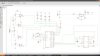
Its a line following robot, using an l339N comparator, atmega328 uC, L293D and IR sensors( which is on an another board).Im finding it really hard to manual route the traces.As far as ive heard autorouting rarely works. Btw im using eagle v5.7.0 (free edition)
Thanks
 

Attachments

  • board4comp2.JPG
    board4comp2.JPG
    178.7 KB · Views: 247
Why not have Eagle do it?

It has an autorouter built in. Read the tutorial.
 
Last edited:
If it routes all the lines, the PCB should work.

Sometimes you have to look at the routing and move some of the components to make the routing easier so it can make all the connections without having to add jumpers.
 
That seems to be a relatively simple routing exercise....or do u need a super small single sided brd?
 
Yes , i want a single sided board. Since im using the free edition of eagle it has a size limitation of (4 x 3.2 inches). Do you think it is possible to route the traces 100% in this confinement?
 
With the LEDs there it will only pull up to about 3.2v (5v -1.8v). That may be ok, but since this is directly attached to noisy DC motors I would use better pullups.

It only needs another 4 resistors, either across the LEDS or from the micro pins to 5v.
 
Hi,

if the autorouter doesn't manage to route 100% you should try a double sided layout.

If it still fails to route 100% you have a flaw (or several) in your schematic design.

I suggest you click each net and look if it is connected to at least 2pins of components. (Net and connected pins should highlight.)

Grid size is very important for the schematic design. Changing grid from e.g. 1/10" (=2.54mm) to any odd value , e.g. 1/10.5 (=2.42mm) the nets don't connect to pins.

Always use integer values for a finer grid, e.g. 1/20", 1/40" etc.

Printing a net list you will be able to compare the result with the intended nets.

Boncuk
 
Last edited:
Thanks for the replies and suggestions, guys :)

With the LEDs there it will only pull up to about 3.2v (5v -1.8v). That may be ok, but since this is directly attached to noisy DC motors I would use better pullups.

It only needs another 4 resistors, either across the LEDS or from the micro pins to 5v.

Actually i had wired the circuit on breadboard without even using the LED pullups and actually it worked fine, out of curiosity, what problems will i face without any pullups?


And heres the schematic file...
 

Attachments

  • board4comp.sch
    162.7 KB · Views: 118
Auto routing has a lot to do with where the parts are placed.
On single sidded boards it is typical to add jumpers where routing is hard. (wires)
What is your sensor? There may be another way with less parts.
 
Remove LM339.
Connect from sensor, through 1k resistor (optional) to micro ADC-inputs. Do the voltage compare in software. Keep the LEDs where they are.
Read ADC, compare voltage, LED on/off, .......
 
When I do a layout (PCB) I often change the sch. to make the layout easy. If sensor 1,2,3 & 4 go to pins 1,2,3 & 4 on the micro it may be better to use pins 4,3,2 & 1. (or pins 9,7,3 & 6) If you can fix that in software.
 
Remove LM339.
Connect from sensor, through 1k resistor (optional) to micro ADC-inputs. Do the voltage compare in software. Keep the LEDs where they are.
Read ADC, compare voltage, LED on/off, .......

I did try that, take the highest and lowest valaue for the sensors and store them in eeprom. But heres the problem ,there were cases when "high" for a sensor was "low" for another sensor. Like, say 3v was high for one pair of IR sensors, 3V was low for another! That is why i added the pot and the comparator so that i could calibrate it individually!
 
Have 4 different values in EEPROM. (4 sensors) Use a UP, down button to set the EEPROM values. You can still calibrate and store each sensor differently.
 
like, connect 5v to a digital pin through a switch,, then program it like, when the digital pin is high, store it in eeprom! ? But programming will get real har and confusing right? with 4 different values for sensors?
 
I don't see any advantage connecting the IR-sensors to an A/D converter.

Since the purpose of the device is a line following robot digital inputs can be used. The sensor outputs can just be high or low - hence used like a switch input into a digital port of the MCU.

Use pull up (or pull down) resistors on the sensor outputs for a defined output.

@jayakrishnan91

Have you checked your schematic for flaws already?

Boncuk
 
Status
Not open for further replies.

Latest threads

New Articles From Microcontroller Tips

Back
Top