Continue to Site

Welcome to our site!

Electro Tech is an online community (with over 170,000 members) who enjoy talking about and building electronic circuits, projects and gadgets. To participate you need to register. Registration is free. Click here to register now.

  • Welcome to our site! Electro Tech is an online community (with over 170,000 members) who enjoy talking about and building electronic circuits, projects and gadgets. To participate you need to register. Registration is free. Click here to register now.

Adjustable voltage regulator controlled by microcontroller

Status
Not open for further replies.

alexchannell

New Member
I have an input source of 12VDC. I need to have a regulated output 0-10V at 1 amp. I have a BX-24 I can use to control it. The voltage will be changed rapidly and frequently. Is it as simple as sending a regulated voltage to a FET or BJT and having the bx-24 varying the voltage to the base/gate?
Thanks!
 
Pretty much. THe question now is how do you get a digital MCU to produce an analog voltage. Google around for PWM DAC. It allows you to use the PWM signal of an MCU and filter it using an RC-filter (or some other filter) to produce an analog voltage dependent on the PWM duty cycle.

However, you are basically making a linear regulator here...and your maxmum power dissipation for your specs is over 10W. Due to dropout voltage requirements, your input voltage will have to be at least ~12V producing 12W of heat in worst case. At 15V input it will be 15W worst case. Even with an excellent 15C/W heatsink and the impossible ideal power dissipation of 10W, that's still more than 150C temperature increase above ambient which destroy all semiconductors at room temperature. At 12W or 15W dissipation, no transistor would survive.

A better method would be to make an MCU-based buck converter.

How rapidly is this voltage going to be changed?
 
Last edited:
That is how I plan to do the control, using the PWM and and RC filter. The BX chip already has the capability to produce a "pseudo analog" voltage through this method.

Thanks for the info about the transistors.
I was looking at the possibility of adapting this: Adjustable step down switching voltage regulator
I'm sure I could remove the POT and wire the microcontroller to adjust the voltage...? Only problem is, it will not go below 1.2V. Maybe another filtered PWM with a BJT tied to the output and it would have to take over for lower voltages?
Time, I would really like the adjustment to be made in the 10ms range.
 
Yes, I am going to use the MCU to make a pseudo-analog voltage to control the regulator.
I thought the standard regulators or transistors might not deal with those current levels that well. I was looking at trying to control one of these with the MCU: Adjustable step down switching voltage regulator
Being that it's around 90% efficient in all voltages I will be dealing with I think it would be an easy solution.
The issue I see with the switching voltage regulator above (and seemingly most other semiconductors) is it won't go below 1.2V Any idea how I can control the voltage level from 0-10? I have many other I/O lines I can use so I'm guessing a switchover to another circuit could be done in software without much hickup. (precision doesn't need to be that good +- .1v is good and a small spike is perfectly fine - the 0-10V will be driving a solenoid that is 6-8 ohm at no load)
 
Okay thanks.

I found a small dc-dc converter that can do 1.25v-10v but it seems none of the dc-dc converters can do < 1.25V any idea on something available to control to 0V?
 
Last edited:
Okay thanks.

I found a small dc-dc converter that can do 1.25v-10v but it seems none of the dc-dc converters can do < 1.25V any idea on something available to control to 0V?

For the most part, 1.25V is the voltage reference used inside the DC-DC converter (usually on chip) and so that is the minimum the converter can provide with regulation.

I agree with the buck converter route, although you could theoretically use an LM317, with paralleled external power transistors. The minimum of that regulator is also 1.25V, but you can compensate for that by using an ICL7660 to create -12V, a resistor deivider to get it down to -1.25, this would cancel out the reference voltage, meaning you could get the output close to 0V. Although you'd still have a hell of a lot of heat to disapate, which may not be prudent for reliable operation.

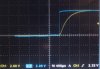
As for a MCU controlled buck converter. Keep an eye on the response time, sometimes firmware can be too slow to adjust the voltage, but for the most part in control apps, its not an issue. Many microcontrollers have onboard comparators with voltage references which would make your life easier. You could of course use an external voltage reference, and a precision voltage divider to get it <1.2V. I believe microchip have an application note regarding SMPS with code included...I'm sure you could adapt this for other micro's though.

Depending on available parts and efficiency, you also might want to look into 'synchronous rectification'. It requires more control, but for such low output voltages it keeps the efficiency sane, as at <2V the voltage drop across the shottky diode in a buck converter becomes significant.

All that said, for simply designing a 0-10V source at 1A that doesn't double up as a heater, it shouldn't be too difficult. Parts only become critical when efficiency and precision regulation is paramount.

Blueteeth

Edit: A quick check over at Linear Technology - Linear Home Page they have quick a few buck regulators capable of 12V in, with down to 0.6V (or less) out @ 2A+, most have integral MOSFETS so the part count is low. LTC3603 for example.
 
Last edited:
Google around for PWM DAC. It allows you to use the PWM signal of an MCU and filter it using an RC-filter (or some other filter) to produce an analog voltage dependent on the PWM duty cycle.

Funny you mention that, I recently revised my **broken link removed**, optimized for 36Khz (so that its out of the audio freq range);
**broken link removed**
note the PIC's power supply/OSC are not shown

Here's the result (not that in the below images, the Yellow Channel is the raw PWM signal, and the Blue Channel is the filtered DAC output);
variable-20pwm-20duty-20cycle-gif.25610


It's a little hard to judge quality from that, so here's some other real life results;

a) Switching from 0% to 100% duty instantly (with short pause in between);
max-20and-20min-20duty-20cycle-gif.25611


b) Closer look a the Time Constant charge time (image displays a ramp from 0% to 100% duty on a 400uS time base);
img45-jpg.25612


c) The only noise left over is the slight ring from the PIC's PWM signal (note the signal is completely flush either side. The time base on this test is 100nS)
img46-jpg.25613


As per usual, all of the source code and information can be found on the site **broken link removed**

:eek:
 

Attachments

  • Variable%20PWM%20Duty%20Cycle.gif
    Variable%20PWM%20Duty%20Cycle.gif
    1.1 MB · Views: 6,720
  • Max%20and%20Min%20Duty%20Cycle.gif
    Max%20and%20Min%20Duty%20Cycle.gif
    954.9 KB · Views: 6,435
  • img45.jpg
    img45.jpg
    12.5 KB · Views: 6,261
  • img46.jpg
    img46.jpg
    17.3 KB · Views: 6,301
Last edited:
Edit: A quick check over at Linear Technology - Linear Home Page they have quick a few buck regulators capable of 12V in, with down to 0.6V (or less) out @ 2A+, most have integral MOSFETS so the part count is low. LTC3603 for example.

Ohh thats great, I think .6 will be close enough to work! EDIT: dangit...looks like every single one is a surface mount type, not fun.

Grammo: Thats fantastic, will defiantly be using your circuit for the PWM output.
 
Last edited:
Hi,

Some things to think about...


An RC filter (single or dual) produces the average voltage of the
PWM signal without too much trouble, but the ripple is dependent on
the RC time constant. A long time constant produces a nice clean signal,
but the response time is slow, while a fast time constant produces more
ripply but the response time is faster.
The design is a tradeoff between these extremes where you try to get
a good smooth signal yet with fast enough response to a change in
external operating conditions.
If really fast time is required a DAC will get you there with fast rise
time and smooth output, but of course is more costly. For high
precision the output is dithered.
For a cheap DAC a 1R2R resistive network may be good enough,
requiring only resistors and possibly one op amp. Even 4 bits will
provide for pretty good results when used with dithering...much
better than pure PWM.
You can also look into a RLC filter, or an RC op amp design for
clean output and faster response.
 
Last edited:
just add 1 or 2 serie's diode (you may loss only about 1-2W) to dc dc converter to go down to 0V, since you will monitor output voltage it won't be a problem even if drop voltage on the diode is not always the same
 
lol oops, missed that one, seems obvious now :( For 1 amp, you'll probably want to use 3A diodes, which are widely available, possibly some TO-220 versions, as you can easily heatsink those to be safe.
 
just add 1 or 2 serie's diode (you may loss only about 1-2W) to dc dc converter to go down to 0V, since you will monitor output voltage it won't be a problem even if drop voltage on the diode is not always the same

I don't think that will really work if the desired function is to be able to supply 1 amp of current at all possible voltages. Do you think that the diodes would pass 1 amp of current at .25 volts output? I don't think so.

Lefty
 
Lefty, I beileve he meant adding two diodes in series before the feedback for regulation. The minimum output of most DC-DC converters, as mentioned above, seems to be around 1.25V. After two silicon diodes at 1amp, this may not even conduct (Vdrop of diodes at 1amp can be 0.8-1.2V), but the converter will compensate but raising the output, into the diodes, until they conduct and provide the required output. So for 0.4V output, the output of the converter before the diodes would be, say 2.2V

Effectively turning a 1.25v - 12V adjustable output to a 0-10V one, with reduced power efficiency, but maintaining regulation (via the feedback loop).

PWM can be added to the feedback loop of these modules to control its output, I have done this myself with great success.

To the op, if this is for a control system with feedback, then 'absolute' voltage/current is essentially meaningless, you simply want the output to react to its input stimulus. But of course you'll need some feedback, like a position/pressure sensor.

Blueteeth
 
How do you get the output below 1.25V?

Take the 'normal' 0V rail below 0V by 1.25V, see the attached for an example.
 

Attachments

  • LM317 0 to 13.8V.pdf
    9.9 KB · Views: 962
Status
Not open for further replies.

Latest threads

New Articles From Microcontroller Tips

Back
Top