Continue to Site

Welcome to our site!

Electro Tech is an online community (with over 170,000 members) who enjoy talking about and building electronic circuits, projects and gadgets. To participate you need to register. Registration is free. Click here to register now.

  • Welcome to our site! Electro Tech is an online community (with over 170,000 members) who enjoy talking about and building electronic circuits, projects and gadgets. To participate you need to register. Registration is free. Click here to register now.

adjustable current booster

Status
Not open for further replies.

zhi_yi

New Member
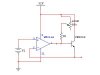
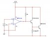
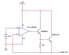
hi, please help me, i have a power supply with output voltage range from 0 to 32 V, and the interval is 1mV per change, and i can give the value of voltage (desire state) to the power supply via keypad, but the output current of the power supply is small since the last stage is an op amp. i want to boost the output current, so, i tried using 2N3055 with current booster configuration, but i found that while the inverting input of op amp connected to the emitter of 2n3055, the V+ become different from V-, and the 3055 is in cut off. so i tried bias the transistor with voltage divider bias, i can boost the output current with that configuration, and i can adjust the output current by change the Ib, but while i change the resistance, the output voltage changed, please help me, i want to boost the output current without any changes of the input voltage.. thanks you..
 
A transistor that is an emitter-follower and that is inside the negative feedback loop of the opamp circuit will work fine. Post the schematic of how you connected it.
 
hi, here i attached the circuit, i use lm324 instead of lm311.

i tried both of them, and also one with voltage divider bias to the transistor, but it seem to be impossible to use voltage divider bias since it affected the output voltage, please correct me.. thanks..
 

Attachments

  • 98_1156909304.JPG
    98_1156909304.JPG
    9.8 KB · Views: 781
  • 51_1156909352.JPG
    51_1156909352.JPG
    11.5 KB · Views: 599
Your 1st circuit should give about 500mA output, but the pot doesn't do anything.

The 2nd circuit has a 1k resistor at the output of the opamp that is overloading it, and has a 3 ohm resistor that is wasting a terrific amount of current. It doesn't need a power transistor as the driver transistor.

I have corrected your 2nd circuit. But since you didn't say how much current you need, I selected a little 2N3904 as the driver transistor whose power dissipation limits the max current to 1A.
 

Attachments

  • Voltage output circuit.PNG
    Voltage output circuit.PNG
    32.9 KB · Views: 650
thanks..

i need the current to be adjustable to Max 3A, the R1K of the op amp i used because sometimes ago i use LM311 instead of LM324, because at that time, i have my LM324 damaged. so, the 1k is the pull up for LM311.

can you please tell me how to calculate the maximum current from 3055 please.
 
The LM311 is a comparator without frequency compensation, not an opamp that has frequency compensation to avoid oscillation. So it cannot be used with negative feedback like an opamp can in your circuit.
The LM324 is a low power quad opamp so has a min output current of only 10mA. With a low output voltage, the 1k pullup resistor needs 30mA which most LM324 opamps cannot supply.

The 2N3055 has a minimum current gain of only about 26 at 3A. So its max base current is 115mA. If the output voltage is 2V then the driver transistor will have 30V and 115mA which is a dissipation of 3.45W and must be a small power transistor with a heatsink.
A TIP31A is a small power transistor and has a min current gain of about 45 at 115mA so its max base current is only 2.6mA which the LM324 opamp can easily provide.
 
i tried the circuit that you provided, but i can't get the output voltage to be equal to the input voltage.

i give 10V to the input (V1). and then i measure the point below with and without load at emitter of the 2N3055, the result is the same:

V+ = 10V
Collector - Emitter of 2N3904 approximately 8V
Voltage of R 1k = 0V
Collector - Emitter of 2N3055 approximately 9V
output (V-) approximately 23V

it seem that the less voltage from Vcc is drawn to the V-, and V- become differ from V+..

Vcc = 32V
Vce = 8V
V at R1k = 0V
32 - 8 = 24V
V- approximately 23V
 
zhi_yi said:
i tried the circuit that you provided, but i can't get the output voltage to be equal to the input voltage.

i give +10V to the input (V1).
OK.

Collector - Emitter of 2N3904 approximately 8V
No. The emitter of the 2N3055 will be +10V and its base about +10.65V. The output of the opamp and the base of the 2N3904 will be about +11.3V.

Voltage of R 1k = 0V
No. it is at the base of the 2N3055 transistor at about +10.65V.

Collector - Emitter of 2N3055 approximately 9V
Never mind what is the collector to emitter voltage. The emitter of the 2N3055 transistor should be the same as the input voltage.

output (V-) approximately 23V
No. It should be the same as the input voltage, +10V.

it seem that the less voltage from Vcc is drawn to the V-, and V- become differ from V+.
What? The voltage from Vcc to ground should not change. It is 32V.
The voltage from V+ to ground also should not change. It is 10V.

Hey! Isn't the - of the 32V supply connected to the - (ground) of the 10V input???
 
Thanks..

i tried it again, but the result is still the same, the emitter of the 2N3055 doesn't give me +10V but +23.4V, base of 2N3055 (emitter of 3904) give me +23V, and the emitter of 2N3055 (V- of LM324) also +23V, so the base to emitter of 2N3055 0V, Collector to Emitter of 3904 give 8V, Collector to Emitter 2N3055 give 8V too. it seem that the transistors have been turned ON, and the current can be boosted, but the voltage of V+ (input) and V- (output) is still different.

yes, the voltage from Vcc 32V doesn't change, and also the Vin 10V.. yes, the ground of 32V supply connected to the ground of the 10V supply.. please help me..

thank you Audioguru :)
 
Could it be that you dont have any load on the emitter of the 2n3055?

If there is no current taken from the output of the circuit, I think the output will just rise up to the supply voltage.

JimB
 
thanks JimB,

but i tried both with and without load on the emitter of the 2N3055. the result is the same. i tried using 2k2 as load
 
It sounds like you heve the pins of the transistors all mixed up. Look at the pictures and descriptions of the pins on the datasheets.
If the emitter and collector of a transistor are reversed then the reverse-biased emitter-base junction has avalanche breakdown like a 6V to 8V zener diode. Then the ouput voltage would be what you measure and the opamp would be getting pretty hot.
 
high current oscillator

Sorry to drag up a years old thread, but I stumbled on this, and the circuit is very similar to something I was going to implement.

I'm trying to build a driver that will produce a high DC current (about 7A) with approximately a 30Hz sinusoidal oscillation of 1A through an inductive load with an impedance of about 5 Ohms at this frequency.

I was going to use basically what was drawn in the corrected schematic however:

a little 2N3904 as the driver transistor whose power dissipation limits the max current to 1A.

I thought the current in a Darlington pair was limited by Q2, the 2N3055 (~15A).

If this is not so, do I just need to biggie up the driving transistor?
 
Status
Not open for further replies.

Latest threads

New Articles From Microcontroller Tips

Back
Top