Continue to Site

Welcome to our site!

Electro Tech is an online community (with over 170,000 members) who enjoy talking about and building electronic circuits, projects and gadgets. To participate you need to register. Registration is free. Click here to register now.

  • Welcome to our site! Electro Tech is an online community (with over 170,000 members) who enjoy talking about and building electronic circuits, projects and gadgets. To participate you need to register. Registration is free. Click here to register now.

Adding push button to 2 way motor circuit

Status
Not open for further replies.

rfeyer

Member
I am actually pretty green at electronics, but was able to build the below circuit successfully with LOTS of help from people.
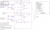
The circuit is used to drive a 12V motor bi-directionally to open a chicken coop door; and the Q1 andQ2 transistors are tripped by a 5v input from a MicroController (in this case Webcontrol 8.0).
It is a sort of Flip Flop circuit (as most of you can easily see I'm sure).
It has been running successfully for months, until I had the bright idea of adding 'local (at the coop door) push buttons to over-ride the Q1 and Q2 transistors with a simple button, thinking that would be all I had to do to get local control of the doors (BTW - the 12V circuit is constant ON - only interrupted by the SW1 and SW2 switches - at top and bottom of door).
The lines in blue indicates where I tried 'jumping' the transistors, again, using a simple push button - attaching line to C and E. However, this, after a few tried, fried the transistors.

Do I simply need to add a Diode to stop revere direction, or is my principle of 'jumping' the transistors totally off base?

Any help would be greatly appreciated as I am stuck.

TY!!
Rainer
 

Attachments

  • upload_2015-8-15_7-42-41.png
    upload_2015-8-15_7-42-41.png
    178.3 KB · Views: 183
I can't see any lines in blue on your diagram. When you say adding a push button I assume you really mean two push buttons. One for up and one for down. I assume that you have wired a normally open push button between collector and emitter of each transistor. If this is the case I can see no reason why its should not work and it should not harm the transistors. Are you sure that that you have connected to collector and emitter and not one of them to the to the base ?

Les.
 
Les - where are the blue lines?
You are correct, I actually uploaded the wrong diagram (without the blue lines added :) ) - TY for pointing out!

You are also correct that I used two push button switches, both normally open, one on the Lower and one on the upper transistors.

Hmm, I will have to take the module apart gain to see the bottom of the board. I thank you for checking the schematics!

Would there be any benefit, or even harm, to place a diode at the collector side of the bush button wire?

Rainer
 
Hi Rainer,
I do not see any point in adding a diode. It would do no harm. (But the button would not work if the diode was connected the wrong way round.)

Les
 
TY Les!

Saves me 2 diodes and extra soddering :)

I do appreciate all your help,

Rainer
p.s.: will update once I take module apart, may take a week
 
I agree with Les. Bridging the collector and emitter with push buttons should work and should not fry the transistors unless the catching diodes (D1,D2) have become disconnected.
 
I remember that circuit. :)

Yes, that will work. Just use two normally open push button switches and bridge the emitter / collector of the transistors. It will allow you to manually turn on K1 & K2. Just make sure you never press both switches at the same time.

Ron
 
Hi Ron,
I don't think pressing both buttons at the same time will cause a problem. both relays will close connecting both ends of the motor to + 12 V The motor will stop but nothing will be shorted out.

Les.
 
Hi Ron,
I don't think pressing both buttons at the same time will cause a problem. both relays will close connecting both ends of the motor to + 12 V The motor will stop but nothing will be shorted out.

Les.

OMG, you are absolutely right and the humor here is I remember that circuit because I went over it with the OP when I made it. I called out the pin numbers for automotive relays and the OP changed that around a little, my original drawing used ladder logic for the N/O and N/C contacts. :) Thinking back the idea was if both transistors were on, nothing would happen.

Ron
 
Thank you all!

Ron!!!! Long time no hear - TY also for the original schematic!

Rainer

Glad it all worked out for you. We sure covered several pages. :) Have a great weekend.

Ron
 
Not shown is any cable inductance as we dont know the distances involved.

YOu can expect the switches to chatter and thus the relay coils to chatter and 8x surge currents on the motor while braking or accelerating and more if changing direction.

WHat EMI coupling can you indicate? shielding or filter might be needed.
 
Tony,
The MicroController is appr 30 feet away from the electronics board (i.e.: the 5v line which activates either transistor.
The relay to motor distance is a mere 24 inches.
I do not know how to give EMI information, hence, I can not answer that question. However, the motor speed is not changed and direction is not ever changed on a whim.
Does this help?
Rainer
 
Well, I certainly must have made a mistake somewhere and again need help:
Not sure if I fried something in the process of adding the buttons, however, currently the above circuit (with and without the diodes being jumped) does the following:
- when I push the buttons (or manually jump the diodes) the circuit works but pulsates every 1/2 second or so, i.e.: on, off, on, off....

Which item, when broken, would cause this to happen?
TY again for any help,
Rainer
 
All you needed to do was place two normally open push button switches across Q1 and Q2 (emitter to collector) as drawn in on what you initially posted. I don't get the diodes being jumped? You can disconnect the Raise and Lower from the uC and the circuit should work just using the push buttons and removing the curcuit from the uC willo isolate it so we can see if it works.

Ron
 
The uC is the signals from the Micro Controller (u = micro and C = Controller). Shown as the Raise and Lower inputs to the circuit.

Ron
 
Got it - I actually have the board disconnected from the uC - and, since it is both sides (up relay and down relay) I would imagine I have shorted something out.
I, as mentioned above, have disconnected the push buttons as well, and still the mototr goes on and off every .5 secs.

If nothing comes to mind which would be the culprit, then I will chalk it up to experience and make a new board.
I am using this **broken link removed** as relays, should be strong enough, yes?

Rainer
 
Hi Rainer,
Making a new board will not solve the problem. You need to identify what is happening. As you are only using the push buttons and both the up and down buttons (I am assuming this as you do not specify.) are behaving in the same way I think the battery is discharged. I think when you press a button the relay pulls in. this causes the motor to starts which puts more load on the battery causing the voltage to drop. The voltage drops to a point where the relay drops out. This removes the load caused by the motor. The voltage now rises to a point where the relay now closes. This then continues. Monitor the battery voltage to see if this theory is correct.

Les.
 
Les,
TY very much for trying to solve the problem - I of course would also be happier to solve it rather than starting from anew!

The board is currently disconnected fro the uC (? MC).
12V are directly connected to power via 12V PS.
a separate 5v PS (neiter are batteries) is used to: either connect to push button (That caused pulsating motor) and afterwards I disconnected the whole pushbutton assembly and, without 5v PS) used both ends of same wire to jump the transistors CE terminals (both outsides). Still, getting pulsation. And, the motor is not getting weaker, just pulsates.
Any help would be appreciated!!
Rainer
 
Last edited:
Status
Not open for further replies.

Latest threads

Back
Top