Continue to Site

Welcome to our site!

Electro Tech is an online community (with over 170,000 members) who enjoy talking about and building electronic circuits, projects and gadgets. To participate you need to register. Registration is free. Click here to register now.

  • Welcome to our site! Electro Tech is an online community (with over 170,000 members) who enjoy talking about and building electronic circuits, projects and gadgets. To participate you need to register. Registration is free. Click here to register now.

Adding a current limit led to my lm723 bench psu

Status
Not open for further replies.
Like the 555, I have so many fond memories with the 723.

Similarly, its simple architecture allows your imagination to customize and design circuits beyond the traditional databook applications
 
Ay Up.
Good to see you found my project usefull mr T.
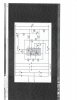
The circuit in post 1 would be the one to build in that case, with the transistor, led & 1k from post 9 for the I limit led, note the accuracy of the led lighting and I limit taking place is approximate within a few ma, but ok for most applications.
I wanted a precision inidiction that I limit was taking place, for various reasons including the fact the supply went quite noisy during I limit, probably due to the high gain of the I sense transistor in the '723.
You right the I sense resistor at 0r22 should be over 2 amps, maybe the current source part of the circuit isnt behaving, try temporarily disconnecting the collector of the current source and see what current you get.
The circuit in post 1 generates a negative supply for the reg chip and the feedback so its adjustable down to 0 volts, the little pot sets 0v output with the V pot at min.
The reg chip doesn have the current as Al said to drive the 2n3055 for long periods, if again you refer to post 1 you'll see theres an intermediate transistor amplifying the output of the '723.
Bc141's are obsolete now, a Bd139 or Mje340 ought to do the job as well.
 
Last edited:
Hi Dr Pepper, Mr Al and all other helpers

I have build the circuit shown in my post. It works quite well and I am happy. Not my design. The problem is that I also need a simple LED indicating current limiting. I tried the arrangement that Mr Al suggested to Dr Pepper with the BC107 or BC 547 as shown by Dr pepper. My tranny is connected in the same way as Dr Pepper except I tried various base resistors but LED stay off. HELP???

TDB
 

Attachments

  • Nice  Circuit LM723.jpg
    Nice Circuit LM723.jpg
    460.4 KB · Views: 300
The doc here.
The circuit in post 9 is very simple, if you just want max current protection or charge batteries it works well.
The circuit does depend on the Bc547/Bc107 being reasonably matched to the transistor in the Lm723.
Triple check all your connections including the Led.
Just an idea, may or may not work, break the connection to the base of the transistor switching the I limit Led and put a 330 ohm resistor inline, and do the same with pin 2 on the Lm 723, put another 330 ohm inline with it.
This will attempt to balance the forward voltages out on the base emitter junctions.
 
Last edited:
Hi Dr Pepper

Thanks for the feedback. I will try the 330R resistors. I also want to make sure I understand correctly. Does the first circuit you have posted, the one with D5 and R5 work ok because I also will try it. Am I correct that if I use this circuit I still need to use your current arrangement LED with the BC107 tranny or BC547 etc. D5 is just a current source LED and does not indicate current limiting as well.

Hope my questions are clear.

Mr T
 
I think I get what you explained.
To be honest that was a while back, and I reworked the circuit and made some improvements so the supply is different to that now.
However I dont remember any problems with it, just that the Led lit up just before, or just after limiting took place, by a few mA.
The triggers comments are valid, stabilisong temperatures of the ext and int trannies is a good idea.
Let us know what you do and if it works or not.
 
Thanks I rechecked my connections against your hand drawn circuit and relized that I must connect the base of the tranny driving the cl LED directly to pin 2 of IC and walla it works nicely now. Again thank you. I get 20V at 2.13A.

Mr T
 
Good for you!
Nothing beats the satisfaction, that comes with solving a problem which you have struggled with for a while.

And this is most important: you will have learned a couple of things you previously didn't know. And like all hard-earned knowledge, you won't forget it.

EDIT: please, please post a schematic of your completed circuit.
 
Very pleased I helped you on this one.
 
Dr pepper,your last schematic is a mess,i was going to make it but find your schematic so poor i cant read it!
 
Apologies.
Good job you didnt have to pay for it.
 
Status
Not open for further replies.

Latest threads

Back
Top