leftfield95
Member
Hi Mike,
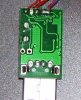
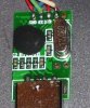
After I lost my old Nokia phone, I decided to convert a fake DKU-5 cable, it too used a Prolific 2303 chip. But it took quite a while to figure out how to make it work, of the five wires in the cable, I had to short all the wires together except the black-GND wire to make it act as a loopback in Hyper-terminal. After that I worked out which pairs had to be shorted to enable the chip so it would TX and RX.
However even when it wasn’t working I don’t think the driver reported any errors. (Win XP SP3)
I can try and find my notes if you want to let you know which pairs I shorted together.
Leftfield95
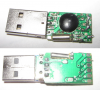
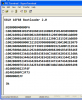
") Even though it shouldn't matter, the cable has no series resistors on its I/O's. I would plug it into your PC, open the device in hyperterminal (or another terminal) *then* connect the Tx to Rx.
Even though it shouldn't matter, the cable has no series resistors on its I/O's. I would plug it into your PC, open the device in hyperterminal (or another terminal) *then* connect the Tx to Rx.