Even if your ADC samples at 9 -16 bits , once u use the hi 8 bits (left aligned) you are working with an 8 bit sample giving 2^8 = 256 discrete values.
I see u are using the ADRESH data which implies you are using no more than 8 bits, otherwise u would be using the ADRESL data as well.
DID u configure the ADRESH/L registers to be left aligned or right aligned?
Getting that wrong will confuse the ADC results.
When i say 'calculate' the binary ADC value i MEAN MANUALLY do it.
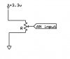
So if u feed in a fixed 2V to the adc input AND u have a 3.3Vdc ref then your ADC value is supposed to be (2/3.3) * 256 ( for an 8 bit adc value)
= 155 .
You can verify this within your code by adding a simple test and lighting an LED. Simply test if for a 2V input: 153<ADC_8bit_SAMPLE<157. Light the LED if it passes.
Then u can apply say a 1V or 3V signal and see if the LED does NOT light, thus verifying the ADC is operational in hardware.