Continue to Site

Welcome to our site!

Electro Tech is an online community (with over 170,000 members) who enjoy talking about and building electronic circuits, projects and gadgets. To participate you need to register. Registration is free. Click here to register now.

  • Welcome to our site! Electro Tech is an online community (with over 170,000 members) who enjoy talking about and building electronic circuits, projects and gadgets. To participate you need to register. Registration is free. Click here to register now.

Adc Pic16f877a

Status
Not open for further replies.
derrick826 said:
hi again, i have tried the codings and it works fine but it seems that the accuracy of 10bit- digital outputs on the LEDs after conversion when compare using the formula:

actual analogue voltage = [digital values in 10 bit (decimal)] * (5v/1023)

is kinda out...

for example: when i input 4.78v into RA0 it gives me 1111111111 (all leds light up)

when i input 0.02v into RA0 it gives me 0000000001 (first led light up)

but according to the formula which i mentioned, the first LED will light up which represent 1 bit if 4.8mv is being applied:

4.8mv = 1* (5/1023)

is there any method which I can do to improve its accuracy from my codings?

hi,
Assuming your supply is +5.0V and your Vref is the same,then

ADC value/bit = 5/1023 = 4.887mVolt

So ADC value,, 0.02/5 * 1023 =4.092 = 0x04 = 00,0000,0100

And 4.78/5 *1023 =977.98 = 0x3D1= 11,1101,0001

It appears the conversion of the ADC is wrong.

This could be due to.

Too high an input impedance that the ADC inout 'sees',,[ keep to =< 4K7 as posted earlier] will cause inaccurate readings,
also ensure that your program meets the ADC acquisition times.

Check the +5V supply and of course you DVM accuracy,
 
derrick826 said:
alright i think i get it .. i have to give it a try first .. thanks for ur comments

hi,
I see from your other thread you are using Oshonsoft, you may find the attached zip handy for debugging the ADC.
Screen shot, I have a number of external modules for the OS

You require the Visual Basic runtime files from the web, free
 
Last edited:
Hi guys again,

it's about the ADC again but now i'm trying to input a sine wave into the RP0 which is the analogue pin of my PIC so that i'm able to capture the digital output of the waveform. I just wanna know if there's any specification of what input i should allow these sine wave to enter the RP0 pin.

I am aware that the sinewave must not be more than 5V and that's for sure but for a sine wave in the X and Y axis, the wave might go below the x-axis and thus giving a negative value and then up the x-axis to give positive value of voltages... is there by chance the negative voltage is able to be converted using ADC in PIC?

I tried the Oshonsoft program with the ADC tool posted above and i input a negative voltage and there's no display on the LEDs
 
I suggest you look at the other similar thread, you simply bias the PIC input to 2.5V with two resistors, and AC couple the signal to the input through a capacitor. This DC shifts the AC signal to 2.5V - but you still mustn't allow the signal to exceed 5V p-p.
 
hi,
I tried the Oshonsoft program with the ADC tool posted above and i input a negative voltage and there's no display on the LEDs

The OS sim will not accept -Vinps on the ADC external module.

i'm trying to input a sine wave into the RP0 which is the analogue pin of my PIC so that i'm able to capture the digital output of the waveform. I just wanna know if there's any specification of what input i should allow these sine wave to enter the RP0 pin.

Which PIC pin are you calling the RP0 pin??? is it the AN0 pin?
As Nigel has explained you have to shift the 'ac' signal as described.
The maximum amplitude is +/-2.5v with reference to centre point of the two divider resistors.

What frequencies are you trying to digitise and why:rolleyes:
 
OMG eric my bad ... it's AN0 lol!!

well i'm actually trying to make an ADC converter which converts any analogue input signals (Sine waves) that goes into the PIC and transmit out the converted data to the PC .

My hardware application is not very strong and i dun really understand what Nigel has explained to me about the biasing thingy with 2 resistors and couple the signal and send it to the AN0 pin.


Why dun i just use a sine wave generator to generate a sinewave with the maximum amplitude of +/-2.5v that straight goes into my RA0 pin?
 
derrick826 said:
OMG eric my bad ... it's AN0 lol!!
Why dun i just use a sine wave generator to generate a sinewave with the maximum amplitude of +/-2.5v that straight goes into my RA0 pin?

hi,
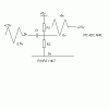
Look at the gif.

If you drive it with +/-2.5Vac direct from a signal generator, you will have to goto the shop and buy another PIC:rolleyes:
 

Attachments

  • Image1.gif
    Image1.gif
    2.8 KB · Views: 118
Last edited:
Oh meaning that
the PIC may be damaged if input voltage is larger than 5 volts or smaller than 0 volts. So with that circuit it actually maintains the analogue signal voltage to a range of 0-5v... Is it correct?

so if i were to do an ADC converter with a really big analogue input range.. how would the circuit be..? surely more components has to be used in that circuit you have drawn for me before connecting to the pin RA0 .

i appreciate your time for drawing the circuit for me! thanks ERIC!
 
derrick826 said:
so if i were to do an ADC converter with a really big analogue input range.. how would the circuit be..? surely more components has to be used in that circuit you have drawn for me before connecting to the pin RA0 .

You simply attenuate the incoming signal to within the +/-2.5V range - just as a multimeter or scope does - so basically just another two resistors as a potential divider on the input.
 
derrick826 said:
Oh meaning that
the PIC may be damaged if input voltage is larger than 5 volts or smaller than 0 volts. So with that circuit it actually maintains the analogue signal voltage to a range of 0-5v... Is it correct?
ONLY with a Vinput of <= +/-2.5V swing

so if i were to do an ADC converter with a really big analogue input range.. how would the circuit be..? surely more components has to be used in that circuit you have drawn for me before connecting to the pin RA0 .

i appreciate your time for drawing the circuit for me! thanks ERIC!

Hi derrick,
I would suggest that you tell us, what is the specific application that you have in mind, else there are so many possibilites.:)
 
okay i just had this in mind.. how about 50v sinewave .. -/+ 25v to the particular circuit that will help me limit my range from 0v to 5v. How the circuit would be? Maybe i can extend the circuit myself if i need a larger range.
 
derrick826 said:
okay i just had this in mind.. how about 50v sinewave .. -/+ 25v to the particular circuit that will help me limit my range from 0v to 5v. How the circuit would be? Maybe i can extend the circuit myself if i need a larger range.
hi,
You could use an attenuator voltage divider to get down from 25Vac peak, to say 2.5Vac Pk.
The ADC AN0 input expects the driving source resistance to be less than 10K, else the ADC conversion value will be inaccurate.

If I had to design a 'front end' for a 25Vac waveform I would use an attenuator, to reduce the voltage,
then a operational amp to level shift the signal, so its always => 0V thru +5V.

The output impedance of the opa driving the AN0 would also be low.

Whats the maximum frequency you had in mind?
 
hi eric

i found this circuit from this site
http://cmccord.co.uk/FYP/5.htm
**broken link removed**

as you can see the analogue input is from 25v to -25v AC... and this circuit streams it down to 0-5v?

i can't think of the frequency right now.. but too high the frequency might not be accurate for the ADC to do conversion for PIC?
 
derrick826 said:
i can't think of the frequency right now.. but too high the frequency might not be accurate for the ADC to do conversion for PIC?

It's absolutely essential that you limit the incoming frequency with a sharp low-pass filter, to less than half your sampling rate.
 
oh ok.. i will take that into consideration as well.. i guess i have to try it to experience it.. thanks nigel and eric! thanks again
 
derrick826 said:
oh ok.. i will take that into consideration as well.. i guess i have to try it to experience it.. thanks nigel and eric! thanks again

You really need to specify what you're wanting to do, being vague about it isn't helping anything.
 
alright nigel... sorry about that.. i wasn't sure about the frequency of the sine wave because i didn't thought about it. but know that you mentioned it already i will bare that in mind. sorry for the trouble guys
 
derrick826 said:
alright nigel... sorry about that.. i wasn't sure about the frequency of the sine wave because i didn't thought about it. but know that you mentioned it already i will bare that in mind. sorry for the trouble guys

Hi,
At point to note are you talking about sinusoidal waves [sine waves] or audio waves etc?.

If its sine waves only, there are techniques that can be used to improve resolution and sampling.
 
i'm talking about the sine waves for now but do other waves (example: audiowave and etc) have the same techniques to improve their resolution and sampling like the sine waves?

i'm also aware that the sleep mode can be activated for the PIC16F877A for better conversion results to digital. So during the initializing starting period of the program, the ADCS1 and ADCS0 must be set to 11 for Frc to enable that feature?

in the data sheet, it is said that to allow the conversion to occur during sleep mode, i have to set the sleep instruction directly after the instruction that sets the GO bit?
 
Status
Not open for further replies.

Latest threads

Back
Top