Continue to Site

Welcome to our site!

Electro Tech is an online community (with over 170,000 members) who enjoy talking about and building electronic circuits, projects and gadgets. To participate you need to register. Registration is free. Click here to register now.

  • Welcome to our site! Electro Tech is an online community (with over 170,000 members) who enjoy talking about and building electronic circuits, projects and gadgets. To participate you need to register. Registration is free. Click here to register now.

AD624 with ECG i need help plzzzz urgent

Status
Not open for further replies.

wavestorm1986

New Member
good day to all
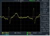
i used the AD624AZ in my ECG circuit and i have few questions to my circuit means that i already got the results and i only need to understand more the idea of how AD624 is working, i go though the data sheet of it but i still have few things to ask like :

1- how much the gain of the circuit below.
2-it's 16 pins there are few pins is not connected why like this .
3- data sheet said that the gain can be set on pin's 13,12,11 !! why then using 3,11,13.
4- if i want to boost the signal more,i mean the voltage i have to use a pull up resistance so what's the best value for that.

i will post the result and and the simulation using multisim 10, any help will be THANKFUL

thanx in advance
Regard's
 

Attachments

  • AD624 WORKING PERFECT.pdf
    86.8 KB · Views: 1,115
  • DS00101.jpg
    DS00101.jpg
    36.2 KB · Views: 989
  • makevol11_0160_fg.png
    makevol11_0160_fg.png
    75.7 KB · Views: 1,163
nuclearrambo
thank u for the response
but i already read the data sheet and i pass by the link u post it. if u do not mind i just hope u can help me to know the list i post it

thanx in advance
 
nuclearrambo
thank u for the response
but i already read the data sheet and i pass by the link u post it. if u do not mind i just hope u can help me to know the list i post it

thanx in advance
hi,
Pins 11,12, & 13 are for setting the FIXED gains as shown on the datasheet.
Pins 3 & 16 are for adding a fixed or variable resistor in order to further control the gain.

Pins 14 & 15 a for Nulling the amplifier, they are not used on this project.

EDIT:
Based on the data the gain is on full at 1000.
 

Attachments

  • AAesp02.gif
    AAesp02.gif
    23.8 KB · Views: 603
Last edited:
datasheet says that gain = (40k/Rg)+1 = (40000/225.3)+1 = 178.5.
i dont know if i am right. but thats what i was trying. i am not an expert, just trying to help.
 
hi,
Pins 11,12, & 13 are for setting the FIXED gains as shown on the datasheet.
Pins 3 & 16 are for adding a fixed or variable resistor in order to further control the gain.

Pins 14 & 15 a for Nulling the amplifier, they are not used on this project.

EDIT:
Based on the data the gain is on full at 1000.

thank u sir for your help
but after i go though the table in the data sheet and you post also, i found that the pin's are 3,11,13 which i couldn't find a match with what i want to find, and something else why there are a connections between 4,5 ??

Regard's
 
thank u sir for your help
but after i go though the table in the data sheet and you post also, i found that the pin's are 3,11,13 which i couldn't find a match with what i want to find, and something else why there are a connections between 4,5 ??

Regard's

hi,
The 10K on pins 4 & 5 is for nulling the inputs.

Pins 16,12 & 13,11 are linked to pin 3,,, Gain =1000
 

Attachments

  • AAesp02.gif
    AAesp02.gif
    24.7 KB · Views: 429
Last edited:
hi,
To increase the amplitude of the signal you could add a non inverting OPA after the filter.
 
thank you guy's so much for your help
but i few things like the CMRR which is have fixed value which is 130dB min, so is it means that i can find the value of CMRR with respect to gain=1000 ?? coz i read the data sheet and i did not find a way to do any math to find CMRR !!


thank you again

Regard's
hi,
The CMRR of 130db applies to gains of 500 to 1000.

If you want to increase the gain to greater than 1000 then

Connect a resistor from pins 3 and 16 [disconnect the others 13,12,11 & 10.]

The resistor value is Rg = 40k/[G-1] , where G= the gain you want up to a maximum of 10,000 times.
 
Last edited:
ok thank you sir
R1=R2= 47k will limit the current from the source to the IC correct ?
the capacitors that connected to the +9,-9 is to smooth out the voltage source to get better signal correct ??

Regard's
 
ok thank you sir
R1=R2= 47k will limit the current from the source to the IC correct ?
the capacitors that connected to the +9,-9 is to smooth out the voltage source to get better signal correct ??

Regard's

hi,
The 47K's will help prevent damage due electrostatic discharge by limiting the current flowing in the input pins.

The decoupling capacitors on the power pins are to reduce any electrical noise thats present on the power rails.
 
LTspice simulator

Hi,

for LTspice simulator what is the input device use for input for ecg?
i will try seach on it

thanks
 
Hi,

for LTspice simulator what is the input device use for input for ecg?
i will try seach on it

thanks
hi,
Look at this link, download suitable audio wav files.
https://www.soundjay.com/heartbeat-sound-effect.html

Then in LTspice use wavefile=C:\filename.wav chan=0 with a Independent Voltage source model.

You can then use the audio file to input heartbeat sounds into your simulation.
 
Last edited:
Status
Not open for further replies.

Latest threads

Back
Top