Continue to Site

Welcome to our site!

Electro Tech is an online community (with over 170,000 members) who enjoy talking about and building electronic circuits, projects and gadgets. To participate you need to register. Registration is free. Click here to register now.

  • Welcome to our site! Electro Tech is an online community (with over 170,000 members) who enjoy talking about and building electronic circuits, projects and gadgets. To participate you need to register. Registration is free. Click here to register now.

ad623an in. amp. constant output!

Status
Not open for further replies.

player1

New Member
Hello Guys,
I am trying to amplify a load cell output signal using ad623 amplifier. I am using a 5kg load cell and its excitation voltage is the same power source of the in. amp. itself.
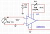
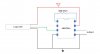
I've made a simulation using Multisim and the output was great. the problem now is in the actual circuit, whatever I do, the output of the ad623 always is constant even if a 0V is applied to its input. any ideas to solve this problem?
 

Attachments

  • ad623.JPG
    ad623.JPG
    52.2 KB · Views: 189
Is one of the inputs grounded in the real circuit, as shown in the schematic?
 
no, should it?
Yes, the inputs needs a ground path for the input bias currents.
Show the exact schematic of the circuit you have built.
 
What is the voltage from load cell?
If it is negative ( + lower than -) AD623 can't handle it with single supply.
The gain with 100 ohm resistor is 1000.
Is it too much?
 
Yes, the inputs needs a ground path for the input bias currents.
Show the exact schematic of the circuit you have built.
The input bias currents come from load cell?
If the minus input is grounded, the load cell bridge will be unbalanced and the plus input is about 0.5*Vsupply.
 
The input bias currents come from load cell?
Yes, the load cell can provide that, so you don't need to ground one of the inputs.
What's the impedance and output voltage from the load cell?
 
the impedance = 990 Ohm
the output voltage = 1 mV/V (from the datasheet), I tried to measure it using a multimeter but it is always = 0 while applying a force on it. is that mean the problem in the load cell itself?
 
I mean what is the output voltage to ground from the load cell, not the differential voltage..
Is that zero volts?
 
the voltage from the green or white wire of the load cell to the ground is also 0v

That sounds like the load cell is faulty or has burned out due to too high a supply voltage.

A full bridge "load cell" is just four strain gauge elements wired in a bridge configuration:
ie. **broken link removed**

The outputs should be at half supply, with no applied load.

The diagonally opposite pairs are configured so one diagonal is under compression and the other diagonal is under tension when load is applied to the cell.

That results in the two outputs being changed in opposite directions by some amount depending on the applied load, so giving a differential output voltage.
 
Status
Not open for further replies.

Latest threads

New Articles From Microcontroller Tips

Back
Top