Continue to Site

Welcome to our site!

Electro Tech is an online community (with over 170,000 members) who enjoy talking about and building electronic circuits, projects and gadgets. To participate you need to register. Registration is free. Click here to register now.

  • Welcome to our site! Electro Tech is an online community (with over 170,000 members) who enjoy talking about and building electronic circuits, projects and gadgets. To participate you need to register. Registration is free. Click here to register now.

AD623 instrumentation amplifier

Status
Not open for further replies.

uceesdp

New Member
Hi all,

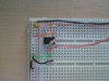
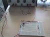
I've just brought the AD623 chip and having trouble trying to produce an amplified signal. From the datasheet, I have built the circuit for basic operations and have chosen Rg to be 100K producing a gain of 2. However, the output does not produce the correct voltage even when varying the resistors.

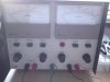
I am using a dual power supply to power the amp and input to the +IN and -IN pins.

Can someone please help me out as i need to use this chip for part of my project.

Thank you

Regards
Steven
 
GENERAL DESCRIPTION:

The AD623 is an integrated single-supply instrumentation amplifier that delivers rail-to-rail output swing on a 3 V to 12 V supply. The AD623 offers superior user flexibility by allowing single gain set resistor programming and by conforming to the 8-lead industry standard pinout configuration. With no external resistor, the AD623 is configured for unity gain (G = 1), and with an external resistor, the AD623 can be programmed for gains up to 1000.


Although the design of the AD623 was optimized to operate from a single supply, the AD623 still provides superior performance when operated from a dual voltage supply (±2.5 V to ±6.0 V).

Since you mention using a dual supply, you are running the voltages as they should be I assume? Also, per the data sheet you are using caps at the power pins correct?

Next, what sort of gains are you seeing for known inputs?

Ron
 
Hi Ron,

My dual power supply powers the amplifier (+Vs = 5V, -Vs = 0V) and the other part acts as the inputs to -IN and +IN (-IN = 0V, +IN = 0-2V). And yes I am using a 0.1uF and 10uF cap at the power pins.

Ideally, when in this case +IN is 2V i should get 4V, but this does not happen at all as i get voltages below 2V at the output.

Also i noticed that the output gradually increases without touching the circuit which i found disturbing.

Thanks

Steven
 
Have you grounded [0v] pin 5 REF.??

Post your circuit diagram.

EDIT:
Try it like this.
 

Attachments

  • AAesp01.gif
    AAesp01.gif
    24 KB · Views: 665
Last edited:
hi,

i've attached my circuit diagram

hi,
You must not have the two inputs floating, there must be a ground reference, it can be a high value resistor.

Connect the inputs as shown in my previous post, you may need to swap over the -in and +in.
 
Hi,

Shown on your diagram, can i use the V3 power supply format connected to -in instead of using V1? because i'm testing on a breadboard and dont have that power supply.

thanks
 
Hi,

Shown on your diagram, can i use the V3 power supply format connected to -in instead of using V1? because i'm testing on a breadboard and dont have that power supply.

thanks

hi,
Do you mean like this.??
 

Attachments

  • AAesp02.gif
    AAesp02.gif
    25.7 KB · Views: 425
Hi,

Picture DSC00132
-the 2 resistors are 1k each in series
-yellow 10uF capacitor
-orange wire is REF leading to ground
-green wire is +IN leading to ground
-red wire going out of the pic is leading to output 2


Output 1 are the power supplies to the amp
Output 2 RED is the supply to the -IN pin
Output 2 BLACK is connected to ground GREEN

thanks
 

Attachments

  • DSC00130.JPG
    DSC00130.JPG
    1.5 MB · Views: 345
  • DSC00132.JPG
    DSC00132.JPG
    1.4 MB · Views: 410
  • DSC00134.JPG
    DSC00134.JPG
    1.4 MB · Views: 333
hi,
Connect the INV input to 0V and the NON INV to +1V, the other way around to what you have.

Be careful not to turn the V2 test voltage too high, say less than +2V, you really should have a 10K resistor in series with the +V from V2 in order to protect the AD623 inputs.

Measure the AD623 output on pin 6.

EDIT,
the way that you had it connected, when only using a single +5V supply, is the +Vinput on the INV pin2 is trying to drive the AD623 output below 0V, which it cannot with a single supply.
Thats why you must use a positive voltage, say 1v on the NON INV pin2, do that the AD623 output goes positive.

EDIT2;
added image
 

Attachments

  • AAesp03.gif
    AAesp03.gif
    36.9 KB · Views: 655
Last edited:
hi,

i think it works, but sometimes dont get the correct results from the output pin 6.

2kohms should give you a gain of ~50. When i applied 0.25V to the input pins the reading showed ~1.75V, it should be about 12.5V.
however, i changed the 2k back to 100k to produce a gain of 2 and i got the correct results but not accurately.

thanks

steven

hi Steven,
How can you get a +12.5V output when using a +5V and 0V supply to the AD623.????
The best I would expect is about +4.5V, at which point the AD623 output saturates.
 
Hi,

My mistake, your right but still 1.75V is no way near the max 4.5V.

If you have a gain of 50 and you input 2V, the internal amplifiers will all saturate and the output will be meaningless.

Dont forget a 10K resistor in series with the +V signal from the power supply, if you accidentally over drive the inputs you could destroy the AD623 due to exceeding the max input current, its in the datasheet.

Tell me what you are using the AD623 for and will be able to help you rather than just guessing...
 
Hi Ericgibbs,

Ill test this circuit more thoroughly at my uni as they got better measuring equipment.

I've got another question to ask. My project involves measuring neural signals which range between 20-50uV from animals. Sometimes, the neural spikes go into the negative region of the scale i.e. -70mV. How would I alter the circuit already designed now to connect to 2 electrodes fitted to the nerve and just amplify the small neural signals to a higher scale such as a gain on 1000 (ad623 max)?

Thanks for your help

Regards
Steven
 
Hi Ericgibbs,

As mentioned before the AD623 is going to be used to amplify neural signals. The output of the amplifier will go into a window discriminator circuit i.e voltage comparator to separate a certain neural signal from the others. The max gain is 1000 which should be enough for the voltage comparator to detect.

Thanks
 
Hi Ericgibbs,

Ill test this circuit more thoroughly at my uni as they got better measuring equipment.

I've got another question to ask. My project involves measuring neural signals which range between 20-50uV from animals. Sometimes, the neural spikes go into the negative region of the scale i.e. -70mV. How would I alter the circuit already designed now to connect to 2 electrodes fitted to the nerve and just amplify the small neural signals to a higher scale such as a gain on 1000 (ad623 max)?

Thanks for your help

Regards
Steven

hi Steven,
If signal output levels of +/-2.0v are acceptable I would connect the REF pin to +2.5V [ 2.5V ref IC's are available].
With this REF offset the output of the AD623 will be +2.5V for no input signal.

Obviously to amplify a +50uV signal to say 2Vout would require a gain of 40,000 which is well beyond the AD623 performance.
If you took the max gain [ for the standard AD623 circuit] of 1000, the 50uV would come out at 50mV.
Study the GBW of the AD623 at these higher gains to make sure that it can handle the high frequency components of the signals.

You could use an OPA to amplify the AD623 output.

Regarding the -70mV that would saturate the AD623 at around -2V

If you want to have an output referenced to 0V, connect the REF pin to 0V and use the NON INV input for the signal, this will give a positive output, the neg spike would just drive harder to 0V. The INV input would go directly to the other electrode via a 10K
Use a 10K resistor in series with the electrode signals.

Does this help?
 
Last edited:
Hi Ericgibbs,

Since i'm only concern with the positive side of the signal I will go with your suggestion, connecting the REF pin to 0V and using the NON INV pin for the signal.

I was also thinking about the same concept regarding adding a op-amp to the AD623 output to amplify the signal further.

For now I only have a function generator to work with in the lab to act as the inputs to the AD623 but later will have a neural signal generator which will put the AD623 to the real test.

Thank you very much for your help, your info has been extremely useful.
 
Status
Not open for further replies.

Latest threads

New Articles From Microcontroller Tips

Back
Top