Continue to Site

Welcome to our site!

Electro Tech is an online community (with over 170,000 members) who enjoy talking about and building electronic circuits, projects and gadgets. To participate you need to register. Registration is free. Click here to register now.

  • Welcome to our site! Electro Tech is an online community (with over 170,000 members) who enjoy talking about and building electronic circuits, projects and gadgets. To participate you need to register. Registration is free. Click here to register now.

AD620 ECG problem

Status
Not open for further replies.

Fluffyboii

Active Member
This got out of hand so I had to ask here. I am aware I am being to dependent on this forum and it is not something I enjoy. I tried solving this problem multiple times with different approaches and failed.

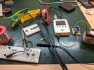
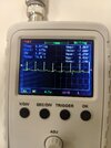
The problem is no matter how much gain I apply and how I filter the signal I can not get anything identifiable that looks like a hear beat on the oscilloscope. Even in the highest sensitivity which is something like 10mV, it is just flat noise with no ECG like component when I connect the props to my arms and leg. I started with AD620 datasheet circuit
1673009730750.png

And went to something as simple as this after nothing I did work.
1673009496273.png

When bottom circuit is tested with a signal generator I can see that It works and I have about 500 times gain. I put a low pass filter to output to set 3db point about 50Hz. Even if I amplify the output 100 times more to a total 5000 with 2 more op amp stages I get nothing. I tried 3 different breadboards, different ICs and checked the connections to props and confirmed that cables weren't open or broken in places. Even with the simplest circuit I should see some fluctuations in voltage with that much gain but instead I usually get 50Hz line noise or something that is about 5-10Hz that is not a heartbeat. Using the top circuit causes op amp to saturate and hit one of the rails even though "ground" is set to the body. Nothing I tried works. At this point I believe the connections are not working because we are not using the cream thing that is supposed to be used with securing the connection to skin.
1673010291287.png

I can not proceed with the project without getting any signal. Any ideas what may be holding me back.
 
T)he diodes, either regular silicon or Schottky's, are there to protect the
inputs from going outside the supply rails. So they allow full CM range
at inputs, only come into action when Vin > 5 + .7 and Vin < -5 - .7

You can experiment with taking more G at input stage than this example.
I would play around with that.

The unmarked R close to A on person, thats 15K. Basically you want
the source Z balanced at both inputs, and also same DC R to not add
a bias current offset at input due to unbalanced DC source resistance.

The 4.7 uF and 1M at output of IA is a HPF .034 Hz. Not sure why that was
done. Or the 220 pF....

1673145302277.png


Regards, Dana.
 
Last edited:
I give up. I am powering my oscilloscope with 12V battery connected to 9V linear converter. I got thick insulated wire for electrodes and grounded its shield. I kept the AD620 gain low and used high pass filter after it to minimize DC being amplified. But the DC off set wont stop ruining my signal. I can put a quartz crystal to inputs and tap over it to create pulses or put a led and see the 60Hz flicker of the lamp shining on it creating pulses on the output. I can measure anything except measuring heart beat. At this point I am better of sticking a piezo crystal on my chest and amplify the sound ffs.
 

Attachments

  • IMG_20230112_144941.jpg
    IMG_20230112_144941.jpg
    8 MB · Views: 147
Last edited:
I may be blind as a bat but I do not see where you tied the top and bottom + rail(red) and
the top and bottom ground rails (black) together ? Note the top red rail seems to have no
components in it so comment here may be irrelevant. When you jumper the ground rails
together make sure you do not create a large loop by doing it at extreme ends of proto board.

Is your lab equipped with florescent lighting, consider turning that off when testing.

The 3 R's used to set G, why not just 1 ? Using that approach to get the desired G that cant
be done with a single R ?

Just for drill make sure your ground rail from extreme left contact to right has continuity.....
it is in fact one buss.


Regards, Dana.
 
Last edited:
I may be blind as a bat but I do not see where you tied the top and bottom + rail(red) and
the top and bottom ground rails (black) together ? Note the top red rail seems to have no
components in it so comment here may be irrelevant. When you jumper the ground rails
together make sure you do not create a large loop by doing it at extreme ends of proto board.

Is your lab equipped with florescent lighting, consider turning that off when testing.

The 3 R's used to set G, why not just 1 ?


Regards, Dana.
Bottom rails are ground and VCC. I used top blue rail for negative voltage and top red rail as another ground to connect shields of input cables. 8K resistor sets the gain and other two goes to leg driving op amp. I noticed that I forgot to put the actual op amp there and connected it directly to my leg which explains why it did not work. I did not sleep for the past 26 hours so yeah...

My breadboards have full connection across its power lanes so no worries there.

Lemme check it again after sleeping I will report back.
 
I may be blind as a bat but I do not see where you tied the top and bottom + rail(red) and
the top and bottom ground rails (black) together ? Note the top red rail seems to have no
components in it so comment here may be irrelevant. When you jumper the ground rails
together make sure you do not create a large loop by doing it at extreme ends of proto board.

Is your lab equipped with florescent lighting, consider turning that off when testing.

The 3 R's used to set G, why not just 1 ? Using that approach to get the desired G that cant
be done with a single R ?

Just for drill make sure your ground rail from extreme left contact to right has continuity.....
it is in fact one buss.


Regards, Dana.
I fixed the problems with the circuit and applied the stuff you mentioned. I get some kind of reading with acceptable off set. I am not sure if it is noise or something else though. I think I may get it right if I get the correct substance to rub on the electrodes.
 
I may be blind as a bat but I do not see where you tied the top and bottom + rail(red) and
the top and bottom ground rails (black) together ? Note the top red rail seems to have no
components in it so comment here may be irrelevant. When you jumper the ground rails
together make sure you do not create a large loop by doing it at extreme ends of proto board.

Is your lab equipped with florescent lighting, consider turning that off when testing.

The 3 R's used to set G, why not just 1 ? Using that approach to get the desired G that cant
be done with a single R ?

Just for drill make sure your ground rail from extreme left contact to right has continuity.....
it is in fact one buss.


Regards, Dana.
I got some sticky electrodes and applied them as suggested on #1 circuit 2 while using single AD620 at 1000 gain. I was finally able to get a reading on those. Using default electrodes on arms still cause the AD620 to saturate. It seems that getting the signal from arms is much more difficult since it is weaker and DC off set is apperent.
 

Attachments

  • IMG_20230113_100815.jpg
    IMG_20230113_100815.jpg
    993.7 KB · Views: 152
  • IMG_20230113_101319.jpg
    IMG_20230113_101319.jpg
    1.2 MB · Views: 171
Last edited:
Your scope shot picture and its measured Vmin and Vmax dont seem to align
with the trace and what I think is the ground reference symbol in the display.....

You AC coupled ? Note if so AC coupled cutoff freq is usually in the 10 - 100 Hz
for many scopes, so take that into account.


1673608912820.png


Regards, Dana.
 
Your scope shot picture and its measured Vmin and Vmax dont seem to align
with the trace and what I think is the ground reference symbol in the display.....

You AC coupled ? Note if so AC coupled cutoff freq is usually in the 10 - 100 Hz
for many scopes, so take that into account.


View attachment 139928

Regards, Dana.
I made the mistake of AC coupling it at low frequency AC signals before and seeing distortion. So it was in DC mode which is indicated on the display. If there is DC bias it shows up there which makes me believe it was the correct mode. Ground mode says GND on display.
 
Keep in mind 4.7 uF one is tempted to use electrolytic, but look at their
datasheet, their tolerance varies in some case > 100%, so choose carefully.
I agree on filter order, start with lower order and increase according to need.

Not sure what governed the input R choices....Got me. Guessing min values
to insure highest transient V applied does not damage IA, eg, current thru input
protection diodes/junctions, the max by degrading input CM Z.....? Eg.
unbalanced R's causing CM error of large magnitude.

Yes on ordinary silicon diodes, small signal I would think, like 1N914....


Regards, Dana.
 
Last edited:
As an aside, here is a BLE design :


More designs :


Regards, Dana.
 
I'm just now getting to this thread. My 1st thought regarding the electrode connectivity issue was to suggest using the sticky TENS unit electrodes. (I had one from physical therapy following an accident.) Replacement electrodes are available at most drug stores and disposable.

2nd thought: if push comes to shove, how about using a contact microphone taped to your chest? Trying to read & register the electro chemical microvoltages responsible for triggering the heart muscles isn't easy considering your source signal is filtered thru dry skin, wet muscle, bone & flesh. Who is to say you couldn't get "interference" from the muscles in between? Try flexing your pecks while it's attached and see if you don't pick up false readings.

Just my 2 cents.
 
I'm just now getting to this thread. My 1st thought regarding the electrode connectivity issue was to suggest using the sticky TENS unit electrodes. (I had one from physical therapy following an accident.) Replacement electrodes are available at most drug stores and disposable.

2nd thought: if push comes to shove, how about using a contact microphone taped to your chest? Trying to read & register the electro chemical microvoltages responsible for triggering the heart muscles isn't easy considering your source signal is filtered thru dry skin, wet muscle, bone & flesh. Who is to say you couldn't get "interference" from the muscles in between? Try flexing your pecks while it's attached and see if you done pick up false readings.

Just my 2 cents.
I actually thought about just taping a piezo crystal over myself since intrumentation amplifier gain is insane it would %100 work if I decreased gain a bit. Two sticky electrodes worked fine and prof. said I can use them so I will probably ditch the arm electrodes. I read the same waveform for short periods of time from my arms but amplitude was greatly reduced and it immediately saturated the op amps after the salty water or cream evaporated from the electrode surface and my arms. It is extremely unstable with those clamp electrodes I think it is not worth trying to use them.
 
I somehow got reading with 3 electrodes. I again used the first circuit from #1 just changed the leg drive op amp feedback filter cap to 1nf and removed series 10K resistor with it. My friend put the electrodes on and it worked nicely like that. 700 gain (100 at TL081 and 7 at AD620) was enough to get a large signal in 0.5V range but I wanted to amplify it more so I put one more amplifying stage and split the gain to 7 at AD620 27 at the second and 27 again for adding a positive voltage so that it gets in the range of 0-5V Arduino needs. I ended up losing some gain at the summing non inverting amplifier so I ended up needing like 5000 times gain. I added high and low pass filters to all stages so it should be 3 order filters for both. 5V zener for overvoltage protection for the Arduino. I should have used inverting summing amplifier then another inverting amplifier but It was too difficult to make it properly so I just ended up adding another TL081 in non inverting configuration. It ended up distorting a bit with all the added stuff so I will probably clean the circuit a bit.
IMG_20230118_175152.jpg


IMG_20230118_175139.jpg
 
The rows of contacts and long wires all over the place on a solderless breadboard guarantees lots of interference and oscillation.
Using shielded audio cables for the probes blocks interference picked up by them (antennas).
 
The rows of contacts and long wires all over the place on a solderless breadboard guarantees lots of interference and oscillation.
Using shielded audio cables for the probes blocks interference picked up by them (antennas).
I am at least using shielded cables to probes. I honestly don't need it perfect, prof only wants a demonstration of that it works and it does enough. I would definitely solder it normally.
 
Last edited:
The age old rule take your G in the first stage is a legit rule for minimizing
noise (this is not your exact application but discussion is appropriate) :


Page 8 specific recommendations.

Also with IA have best Voffset compared to your OpAmps then not Ging up
that Voffset with lots of G in that stage makes more sense.


Regards, Dana.
I can't really increase the gain of the AD620 since it also amplifies the DC off set of the electrodes and saturates with more than 10 gain. But I can get 100 gain at second stage and something like 2 at the last. Would that be more appropriate.
 
Last edited:
The rows of contacts and long wires all over the place on a solderless breadboard guarantees lots of interference and oscillation.
Well, the usual response from AG.
I think that the expression "susceptible to interference and oscillation" is more appropriate than "guarantees lots of interference and oscillation"

If the late Bob Pease can do his prototyping like this:

images


I am sure that Fluffy is OK with his plug-in breadboard and a handful of components.

JimB
 
Status
Not open for further replies.

Latest threads

New Articles From Microcontroller Tips

Back
Top