Continue to Site

Welcome to our site!

Electro Tech is an online community (with over 170,000 members) who enjoy talking about and building electronic circuits, projects and gadgets. To participate you need to register. Registration is free. Click here to register now.

  • Welcome to our site! Electro Tech is an online community (with over 170,000 members) who enjoy talking about and building electronic circuits, projects and gadgets. To participate you need to register. Registration is free. Click here to register now.

AD595-AQ, TCs, PID Control (Heating), and the Arduino

Status
Not open for further replies.

Dacr0n

Member
Hello fellow tech heads.

Well I'm back at it again. In search of some simple proportional control, this time not to heat anything specifically, just heating an assortment of little nichrome elements for experience sake.

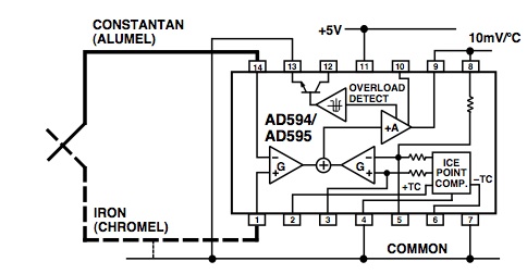
I will be sensing temp with a TC that is being read and amplified by an AD595-AQ. The element driver is going to be a mosfet driven by PWM via either a relatively simple circuit or (if I can find an adequate script) my Seeeduino (dupe of "Arduino Diecimila").

Ideally I would like to use the Seeeduino, but I think I am going to go for the simple circuit first, seeing as how I am not proficient in C.


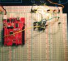
I've attached a few photos of the circuits that I've been playing with. The AD595 circuit attached is setup on the breadboard awaiting my next move.

I've played around with it and do get about 10mV/C so about .300 volts @ 30 degrees Celsius.

What I am wondering now is... What is the best method for taking the TC reading( AD595 output) and having a circuit that compares that to a setpoint ( like setting thermostat) in the form of mV (Ex: 1500mV) and based on the error read between the actual voltage and the "set" voltage, drives the output PWM signal in search of satisfying the target.

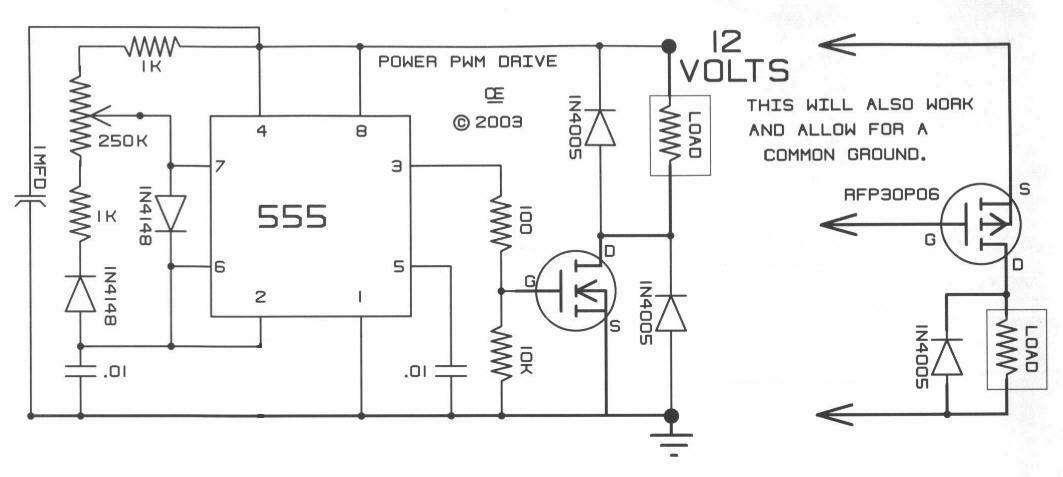
I was thinking of trying to mess with a few opamps as comparators then feed that into the 555 PWM drive circuit. I am going to guess that the input is pin #7?

Thanks much for looking at this everyone... These forums rock!

Here are the photos.

board-jpg.29392


pwm-1-jpg.29389


bb-jpg.29394
 

Attachments

  • PWM-1.jpg
    PWM-1.jpg
    46.5 KB · Views: 11,935
  • board.jpg
    board.jpg
    39.7 KB · Views: 7,340
  • bb.jpg
    bb.jpg
    277.9 KB · Views: 7,741
Last edited:
You have the Arduino why are you using the 555?!
You can use a logic level mosfet or a seperate mosfet driver to drive the FET directly from the Arduino, you'd feed the AD595 into the Arduino and it would produce the PWM output itself.

In the above breadboard picture what is the Arduino even doing?
 
Well.. so far I've got the AD595's output going to ANALOG 0 on the board.

I guess the next step would be to hook the mosfet to one of the digital outs to supply the PWM signal?

My problem lately is been trying to find a script to do what I want...

I've looked at the 3 examples on the arduino PID library and most seem to be over complicated for what I need..
 
Last edited:
I have worked with the Arduino Duemilanove and there are pins on the digital output side specifically labled PWM as their special functions.

For sample programs to look at, are you looking at the analogin samples? Are you using the provided Arduino programming studio (Its a funky green color)?

There is one of the analogin samples that will output the values to an application like hyperterminal in Windows so you can actualy look at the input values then get a feel for the thresholds you need to check for in code.

So you could actualy run the temperature up and look at the values read from analog0 in real time.
 
Okay... So i've got the basic PID script loaded and working on the board.

Now.. I just need to hook up the output to the mosfet and give it a try.

I've already tried monitoring the PWM output (#3) and I can see the power increase and decrease as I mess with the temp of my thermocouple.

Now one problem I am foresee already is the sample rate for the PID script.
Currently its set to 1 second sample rate like so:

void SetSampleTime(int); // * sets the frequency, in Milliseconds, with which
// the PID calculation is performed. default is 1000

What I really need it to be able to change it to sample like at least 5 times a second. Almost like real time.... know what I mean?

Like how the airflow meter on a car is constantly effecting the mixture.

Where can I modify the script to change that?

would doing this change it at all:

void SetSampleTime(250);

Or is there another place I can change it?
 
I'll tell you what. Please post your whole script and ill show you what you need to change.

There should be a main loop in the thing. If you want to sample it in almost "real time" you simply do your reads in the main loop. This will take samples at almost the speed that the microcontroller runs at.


The thing you posted.

"void SetSampleTime(int); // * sets the frequency, in Milliseconds, with which
// the PID calculation is performed. default is 1000"

Looks like a prototype for a function, not actualy how your setting it. Did you get this from a .h file? If you change int to a number in the above code, the compiler is going to throw a syntax error. Somewhere in the code later on, you should see

SetSampleTime(some number here);

If you were to enter 5 there for instance, it may change your sample rate to 5 milliseconds. I need to see the whole thing to know whats going on. If you post it i'll be glad to help.
 
Thanks a lot for the help tech.

Its been many years since I've played with the C language but I think I might have got it going and at least sort of in the direction I want to go.

Here's what i've got so far.. I've added in:
myPID.SetSampleTime(250);
:

Now, while running the script on the board, I can see that the intensity of the PWM output changes much faster now instead of just one second increments.

Sweeeeet!

___________________________________________________________________________________________
/********************************************************
* PID Simple Example
* Reading analog input 0 to control analog PWM output 3
********************************************************/

#include <PID_Beta6.h>

//Define Variables we'll be connecting to
double Setpoint, Input, Output;

//Specify the links and initial tuning parameters
PID myPID(&Input, &Output, &Setpoint, 2,5,1);

void setup()
{
//initialize the variables we're linked to
Input = analogRead(0);
Setpoint = 100;

//turn the PID on
myPID.SetMode(AUTO);
myPID.SetSampleTime(250);
}

void loop()
{
Input = analogRead(0);
myPID.Compute();
analogWrite(3,Output);
}
_____________________________________________________________________________________________________


So another thing I would like to toy with is the output limit.

I notice in PID_Beta6.h:

void SetOutputLimits(double, double); //Tells the PID what 0-100% are for the Output


So to set a limit I simply write in the same place I added in the "SetSampleRate",

myPID.SetOutputLimits(0,70);

? or something like that... if I want to max it out at 70% output?


Thanks again!
 
Last edited:
Based on what you provided Im guessing you would include your

myPID.SetOutputLimits(0,70);

inside the setup function underneath
myPID.SetSampleTime(250);

I'm suspecting that the way you have SetOutputLimits from 0 to 70 wont give you 70%. My guess is that it means the range of analoginput values that will be acceptable. So when you use

Input = analogRead(0);

to read the analogin zero pin, I think by saying SetOutputLimits(0,70) your only going to accept values from 0 to 70. I think the analog inputs on an arduino you should see values from 0 to 1223? So if you only use 0 to 70 you might be cutting yourself short.

Also I'm still not sure exactly whats going on in myPID, but it looks like your sample time is now every 250 milliseconds.
 
Status
Not open for further replies.

Latest threads

New Articles From Microcontroller Tips

Back
Top