Continue to Site

Welcome to our site!

Electro Tech is an online community (with over 170,000 members) who enjoy talking about and building electronic circuits, projects and gadgets. To participate you need to register. Registration is free. Click here to register now.

  • Welcome to our site! Electro Tech is an online community (with over 170,000 members) who enjoy talking about and building electronic circuits, projects and gadgets. To participate you need to register. Registration is free. Click here to register now.

Actuator Stall Problems

Status
Not open for further replies.

stolzie

New Member
Hi Everyone,

I have got a problem that I am not sure how I can solve and need advice on possible solutions.

I have a actuator HK-DZT-03 that I am using to raise and lower a board. The actuator is shown in the following link.

**broken link removed**

The actuator is currently being driven from a relay (ACT512) which is switched via a ULN controlled via a PIC. The PIC also has a current sensing circuit which monitors the current draw from the actuator to determine if we have reached full travel when the limit switches are reached.

The problem that I am experiencing is that I am getting a massive spark across the relay contacts when the actuator stalls. I have tried to catch with firmware the increase current before the stall but it still happens every now and again. I am assuming it is counter EMF generated by the motor producing this spark.

I am thinking that I can either put a transorb or a varistor across the relay contacts to eleminate this counter EMF.

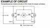
I have attached a basic example of the relay configuration.

How would I go about calculating the value I require? Are there set formulas to calculate this is is all hocus pocus?

Any help would be greatly appreciated.

Thanks,
Jason
 

Attachments

  • DCMotorRelayDrive.jpg
    DCMotorRelayDrive.jpg
    23.2 KB · Views: 171
So my read is you intentionally run the actuator motor into a stall? I did look at some data for the relay, since it is enclosed how do you see the contacts arcing? Not that it matters much. When the motor is driven into a stall how much current does it draw? I would guess a geared actuator motor driven to a stall draws quite a bit. Heck, the bit of data on the actuator beyond a 24 VDC motor makes no mention of current that I could find let alone stall or locked rotor current. There is a possibility that the current draw is exceeding the relay contact ratings. Do you know the stall current? Why drive the actuator to a stall?

Ron
 
Curious what power supply you are using? What is the weight of the load being moved by the actuator? The motor should not stall at end of travel due to limit switches and CEMF should reduce the load current if the motor is reaching any rpm at all. I suspect the relay contacts at this point but lots of other variables that could cause problems.
 
For testing we have intentionally stalled the motor, as this can occur out in the field if it is not used properly(jammed board). When the actuator is raising it draws about a maximum of 3A, lowering is obviously less, the current never gets any higher until put into a stall where it reaches above 8A. We have the firmware monitor this current and anything above the 8A we stop the actuator however when stopped the back EMF is sparking across the soldered terminals on the bottom of the relay. This spark is quite visible.

When testing we did put a 0805 100nF 50V cap across the motor terminals to stop the spark and this basically exploded when the stall occurred. Not a great idea. :confused:

I am not sure what the stall current of the actuator is will have to do some more testing.

We are running directly off a car/truck battery. The weight of the load is about 20kg so it is not heavy.

Thanks for the replies,
Jason
 
Your pic doesn't show any limit switches. How are they being used?
Do you have snubbers across the relay contacts as well as across the motor terminals?
 
For testing we have intentionally stalled the motor, as this can occur out in the field if it is not used properly(jammed board). When the actuator is raising it draws about a maximum of 3A, lowering is obviously less, the current never gets any higher until put into a stall where it reaches above 8A. We have the firmware monitor this current and anything above the 8A we stop the actuator however when stopped the back EMF is sparking across the soldered terminals on the bottom of the relay. This spark is quite visible.

When testing we did put a 0805 100nF 50V cap across the motor terminals to stop the spark and this basically exploded when the stall occurred. Not a great idea. :confused:

I am not sure what the stall current of the actuator is will have to do some more testing.

We are running directly off a car/truck battery. The weight of the load is about 20kg so it is not heavy.

Thanks for the replies,
Jason

Here are the relays you are using for switching the motor load:
N.O.: 20 A 14V DC, N.C.: 10 A 14V DC

That being for a resistive load. At 8 amps when those contacts open you are at 80% load on the contacts and again, for a resistive load which you do not have. I can understand the relay contacts being upset and likely having a short life, maybe weld themselves together which will really make a mess. You can try an RC Snubber type design across your motor terminals and see if that helps. However, I would be looking towards a relay or contactor with much higher rated contacts for your testing.

Just My Take
Ron
 
Your pic doesn't show any limit switches. How are they being used?
Do you have snubbers across the relay contacts as well as across the motor terminals?

There are currently no snubbers across the relay contacts, this maybe something that needs to be implemented to avoid some problems. The limit switches are built into the actuator so at full travel of the actuator the motor automatically stops. I would have to pull an actuator apart to see what is going on inside.

Here are the relays you are using for switching the motor load:
N.O.: 20 A 14V DC, N.C.: 10 A 14V DC

That being for a resistive load. At 8 amps when those contacts open you are at 80% load on the contacts and again, for a resistive load which you do not have. I can understand the relay contacts being upset and likely having a short life, maybe weld themselves together which will really make a mess. You can try an RC Snubber type design across your motor terminals and see if that helps. However, I would be looking towards a relay or contactor with much higher rated contacts for your testing.

Just My Take
Ron

Thanks for the feedback Ron. Higher rated relays may be on the cards if the RC snubbers don't work. I just find it really interesting that every time it hits this condition it produces a spark. Luckily our application is not used in a highly flammable area.

I would be looking at doing it with MOSFETS

This could also be an option to look at for future designs and upgrades.

Thanks everyone for the feedback it is greatly appreciated.

Jason
 
I work for a vehicle manufacturer, and we are not allowed to put freewheel diodes across relay coils like that, because they can cause the relay contact to open too slowly. In your application, the diodes would also add to the delay from detecting the stall to stopping the motor, allowing the motor current to increase more.

Those relays are rated to pull in at 7 V and drop out at 1 V. When the relay is first energised, it will have less inductance, so the current will rise faster. The current only has to get to 7/12 ths of the final value before the relay pulls in. When the relay is turned off, the current has to fall to 1/12 of it normal current before the relay drops out, and that would take around 3 times as long. It could even take longer as the relay will have more inductance in that state.

You should fit a resistor of about 10 times the coil resistance in parallel with the coil. You can put a diode in series with that resistor if you want. The resistor will limit the voltage to around 120 V, which should be fine for whatever is driving the coil. Yours circuit shows switches, but you said that there is a PIC sensing the current, so there has to be a transistor driver somewhere.

This application note describes the problem and suggests a zener diode. https://www.te.com/commerce/Documen...v&DocNm=13C3264_AppNote&DocType=CS&DocLang=EN
 
Thanks for the information Diver, very interesting read from the attached application note. Just goes to show that designs can be implemented and further refined. Just knowing where to find this information.

I have attached the schematic for both the actuator drive and the current sensing circuit. When stalled a spark is produced across the ACT1 /ACT2 terminals. I think that this occurs due to the fact that relay contacts are not entirely synchronized and that there is no where for the EMF from the actuator to go. I have dropped the maximum cut off current down from 8A to 6A and have noticed it is not as bad but still does occur.

Thanks,
Jason
 

Attachments

  • ActuatorDrive.jpg
    ActuatorDrive.jpg
    348 KB · Views: 168
Hopefully you use the limit switch to prevent end stop stall current which may be 5x operating current.
Imax is determined by ESR of motor and Vcc.

For in-between end-limit occasional stalls, one can use a PTC fuse value that does not limit normal load current. e.g. 2A just like power windows and windshield wiper motors.

You must have considered that each output of the ULN is rated max at 500mA and 300mA per driver.

A MOSFET with SCR overcurrent clamp would be better with dual Zener or bipolar MOV protection without uC intervention. Joule rating must >VI*tmax or >LI² of motor for stall current, I.

Relay contacts won't last long if they have to break stall current often.

A 10A bridge can also be used for bidirectional control with PWM soft limiter with 100uH coil and plastic film cap.
Use twisted pair wiring with ferrite CM choke for EMI control.

Relay spikes also create a lot of EMI , even with addition of flashover clamp.

ULN never got hot?
 
Status
Not open for further replies.

Latest threads

New Articles From Microcontroller Tips

Back
Top