Problem: I have a (5) 29Vac power signals from a air handler that I need to monitor with a device that can handle 3-12 Vdc and would like to keep the components down to a low cost low form factor.
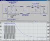
First circuit idea that was given to me was a 1N4001 diode in series with a 100uF capacitor which netted me 39Vdc from cathode to common.I tried coming up with resistors to drop the voltage but ended up getting dc and ac as well. I was thinking about using zener diodes to regulate down to say
5Vdc but am unsure where to go with it.
Also thought about a 4 lead rectifier chip I saw at RS but unsure what to do with it.
I doubt the load is very much to trip the sensor module 500mA's I guess.
I am a little (or alot) rusty on as I got my BSEET 20 years ago and haven't put it to use.
 iode bridge smoothing.svg - Wikipedia, the free encyclopedia
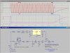
")