Continue to Site

Welcome to our site!

Electro Tech is an online community (with over 170,000 members) who enjoy talking about and building electronic circuits, projects and gadgets. To participate you need to register. Registration is free. Click here to register now.

  • Welcome to our site! Electro Tech is an online community (with over 170,000 members) who enjoy talking about and building electronic circuits, projects and gadgets. To participate you need to register. Registration is free. Click here to register now.

Ac To Dc Conversion

Status
Not open for further replies.

windozeuser

Member
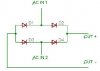
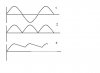
Hi I was Wondering the Most Simpliest cirucit of Turning 120 VAC To Pure VDC :D

I Belive It's Called Rectifacation if i spelled that right :oops:

I Want To Use A step Down Transformer To Change The 120 VAC To 12 VAC Then Covert it into Pure 12 VDC

Can Any One Draw Up A Simple Circuit Of Changing 12 VAC To Pure 12 VDC
THANKS
 
A bridge rectifier:

Of course, use diodes that are up to the task - voltage, current you want them to drive.

You can buy complete bridge rectifiers in a single 4-pin package

Its best to put a capacitor on the output to smooth the DC
 

Attachments

  • bridge_rectifier.JPG
    bridge_rectifier.JPG
    10.8 KB · Views: 1,362
You are right. Rectifier converts AC to DC.
Following schematic is that of a siple bridge rectifier with capacitor filter. With this you can get good ripple free DC output.

For still better and regulated +12V output use voltage regulator IC like LM7812.
 

Attachments

  • rectifier_571.gif
    rectifier_571.gif
    3.7 KB · Views: 1,451
Thank's For Your Replies i didnt realize how easy it really is!! :D

Ya I Think it should be regulated and fused im building a 12 volt accessary box so i can plug in accessaries that would normally be run from a cig. lighter from a car but gonna use them in my house

Whould This Regulator Work From Rat Shack It Has A 12 VDC OutPut And Max 35 VDC input, probably needs a heat sink lol

7812 fixed voltage regulator

Thanks!!! :D [/url]
 
Yes that will work. But keep in mind to make this regulator work properly, your input voltage needs to be atleast 3V greater than what you are expecting at the output or the regulated output voltage.
For 12V output your input voltage should be atleast 15V.
 
So If I Was Running 12 volt's Through the regulator and if there was a power surge it well still keep it a 12 VDC Output Unless The Max Input Voltage of the regulator is exceded (Up to 23 volt's more) and it fry's lol?

Is this like the Regulator in a alternater in a car It keep's the Output at a steady 13 to 14 volt's if the alternator like output's say 16 volt's +
 
So If I Was Running 12 volt's Through the regulator and if there was a power surge it well still keep it a 12 VDC Output Unless The Max Input Voltage of the regulator is exceded

Yes, this is the general idea of a voltage regulator. And yes, the regulator in a car peforms a similar function (though the internal working is quite different to a 7812).

If you plan to dissipate a large amount of power in your regulator, then, yes, it will need a heatsink. For small applications, though, it is usually not necessary.
 
How can a capacitor smooth the DC Signal? I know it's better to put it in parallel with the output (that's the way we learned it in basic electronics) but why?
 
Say you have a AC voltage like in figure 1

The bridge rectifier will cut off the negative side of this sinus and put it on the positive side (figure 2)

This is DC, but as you can see, a bumpy one
The capacitor will get charged at the moment the sinus is at it's peak and discharge itself when the sinus gets smaller again. This way it "fills" the holes in between

sorry for the bad drawing - done in a hurry
 

Attachments

  • sinus.JPG
    sinus.JPG
    15.7 KB · Views: 1,198
Exo said:
sorry for the bad drawing - done in a hurry

Actually I thought it was a pretty good drawing, explained it well!.

One point to mention is that the degree of smoothing depends on the size of the capacitor, the current drawn from it, and the frequency of the supply.

The capacitor acts as a simple battery, providing power when the rectified AC voltage drops - a capacitor is defined as:

'A device for storing energy in the form of an electro-static field' - that comes from a LONGGGGGG time back :)
 
Thanks for all your replies :D One Last Question How Do U Figure out what size cap u need for any applacation is there a math formulae?
 
windozeuser said:
Thanks for all your replies :D One Last Question How Do U Figure out what size cap u need for any applacation is there a math formulae?

I'm going to make a few reasonable assumptions here:

1) You are in fact using 120V 60Hz voltage as your input.
2) You are indeed using a bridge rectifier as shown above.
3) Maximum load current is going to be 1A (this is the max you'd get from a 7812 regulator)

Looking at the data sheet for the 7815 (https://www.onsemi.com/site/products/summary/0,4450,MC7815A,00.html) we see that it has a dropout voltage of 2.0V typical. We're going to add a margin of safety here, and make sure that we're always going to be above that threshold by having a minimum input voltage of 16V.

Since 120V is an RMS voltage, we need to convert it to a peak-to-peak voltage by dividing by multiplying by sqrt(2). If you really want to understand the math behind that, use google, otherwise, assume it to be true. This gives us approximately 170Vpp coming in from the wall.

If we get a 9:1 transformer, this will give us 18.8Vpp coming out of the secondary. We then have to take into account the voltage drops in the dioes, which for a bridge rectifier is 2 * Diode Drop. For silicon diodes, Vdrop=0.7V roughly. This means that we're getting around 17.4V

If we have 17.4Vpp coming from it, and we want a minimum of 16V coming out of our rectifier, then our Vripple = 1.4V. This gives us all the variables we need.

Note: Since the bridge rectifier is a "full-wave" rectifier, it has a ripple frequency of 120Hz, since it is working on both the positive peaks and negative peaks.

The formula for ripple voltage is:

Vr = I / fC

or, in words:

Vripple = Max Current / ( ripple frequency * Capacitance )

Re-arranging this, we get:

C = I / (f * Vr)

and plugging values in, we get:

C = 1 / (120Hz * 1.4V)

C = 0.005952 F = 5952uF = rougly 6000uF (a somewhat commonly available value)

The 6000uF capacitor will give you roughly what you're looking for, but if you want the voltage to be a little more stable, then go for a larger value. Jameco has a 4700uF 25V capacitor for a little over a dollar, and two of these in parallel would be ideal.
 
windozeuser said:
Thank's for all ur replies im going to buy a 16 to 18 volt transformer today


THANKS

Try to get an 18. You'll have better results (as seen above)

If you get a transformer that puts out 16Vp-p, you're going to be coming really close to the cutout voltage on the regulators (because of the 1.4V drop from the diodes)
 
Thank's Tony :D

Wouldnt the Recifier drop 2.8 volt's 4 * 0.7 assuming it has silicon diode's

Probably need a 18 to 20 volt transformer to be safe i guess
 
windozeuser said:
Thank's Tony :D

Wouldnt the Recifier drop 2.8 volt's 4 * 0.7 assuming it has silicon diode's

Probably need a 18 to 20 volt transformer to be safe i guess

No, because current is only going to be flowing through 2 diodes at a time. If you want me to sketch you out a picture, it's not a problem.
 
ahh so 2 diodes are for the negative cycle and 2 diodes are for the positve cycle

a picture might help me lol im kinda one that learns with sound and images rather than words
 
windozeuser said:
ahh so 2 diodes are for the negative cycle and 2 diodes are for the positve cycle

a picture might help me lol im kinda one that learns with sound and images rather than words

Sure, I'll sketch one up for ya. Give me a few minutes. But yes, you have it right.
 
Status
Not open for further replies.

Latest threads

New Articles From Microcontroller Tips

Back
Top