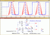
So here is my final attempt. The Input I(Rb) is a 50Hz sinusoidal current burst (15 pulses) that starts at 100ms and ends at 400ms. The simultion is repeated with the amplitude of I1 stepping from +-50mA to+-350mA in steps of 50mA.
The current is converted to a voltage by the burden resistor Rb. U1 and U2 are a full-wave rectifier that creates the full-wave rectified signal at V(fw). The average value this signal is proportional to the input current, but has its first ripple component at 100Hz.
We need a filter U3 U4 that smooths V(fw) to get rid of the 100Hz ripple, but settles within 100ms. It takes a 4th Order Bessel LPF to do that.
You need Rail-to-Rail IN/OUT 1MHz 3.3V opamps to pull this off.
I would like to see you repeat this simulation in Multisim, including the filter rise-fall response. I think that LTSpice is far superior to Multisim in setting up a complex analysis like this. Note how easy it is to start-stop the sinusoidal current, and to repeat the sim at multiple amplitudes. For the students of LTSpice, I am including the .asc file so you can run this sim.
View attachment 104764