Continue to Site

Welcome to our site!

Electro Tech is an online community (with over 170,000 members) who enjoy talking about and building electronic circuits, projects and gadgets. To participate you need to register. Registration is free. Click here to register now.

  • Welcome to our site! Electro Tech is an online community (with over 170,000 members) who enjoy talking about and building electronic circuits, projects and gadgets. To participate you need to register. Registration is free. Click here to register now.

AC LED Circuit

Status
Not open for further replies.

David P

New Member
I have a Hometics Zen table-top water fountain consisting of a small AC water pump that circulates water through a display. I want to add some LEDs to brighten up the unit. Before I construct an LED circuit I'm looking for some expert technical advice.

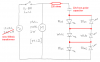
The display right now has a wall-mounted 12 Vac 200ma transformer. At no-load voltage it puts out 16.1 Vac. The 12 Vac 2W motor is connected through a switch to the transformer. I want to add two opposite polarity series legs of two blue and one white LED in parallel with the motor. A capacitor in each LED leg drops any excess voltage. I realize that I won't get full brightness due to the a lesser RMS voltage compared to a plain DC circuit.

The blue LEDs have a 3.5 volt drop at 20 ma. The white LEDs have a 3.5 volt drop at 30 ma. Assuming 20 ma current through each leg and no-load output, I calculate a 5.6 Vac drop across the capacitor. At 60 Hz, that's 280 O impedance; a 9.5 microfarad capacitor should drop the correct voltage.

My questions:
1. Am I out to lunch with my circuit? I'm reaching back to my Navy days with AC circuit theory, so I'd like a backup here.
2. Is my capacitor value close?
3. With a 10 ma operating current difference, will the white LEDs even light? Or will the white LED overdrive the blue LEDs?
4. Will there be any issue with each LED leg during the reverse AC cycle?

Thanks for everyone's help with my first circuit engineering in years.
 

Attachments

  • AC LED schematic, large.pdf
    200.3 KB · Views: 2,102
A capacitor will reduce the current (not the voltage) if the load is AC. But LEDs are DC so the capacitor will charge on the first forward voltage half-cycle of the AC then it will not discharge when the AC voltage reverses so the capacitor will not have current anymore and the LEDs will be dark.

The max allowed reverse voltage for an LED is 5V. In series, the LEDs will not share the reverse voltage equally so one or two might be zapped.

Your little transformer is already overloaded by the motor anyway.

Use a more powerful transformer and connect the LEDs in reverse-parallel and in series with a current-limiting capacitor or resistor. Then one set of LEDs will be forward-biased and will light on one half-cycle of the AC and the other set of LEDs will be forward-biased and will light on the other half-cycle of the AC.
Since the LEDs are connected in reverse-parallel then the max reverse voltage is only 3.5V for each LED which is fine.
 
1) Your circuit only needs a few tweaks. Use ONE nonpolar capacitor, with both LED strings in parallel in opposite directions as you show them.
2) Calculations for the capacitor value are complex (pun intended); your value looks like a good start but fine tune it after measuring the actual current. Beware that cheap NP electrolytics have wide tolerances so plan to experiment.
3) All of the LEDs in each string will get the same current. If the string gets 20 mA, then the white LED just won't be as bright as you expect. Hopefully no big deal.
4) As ag said, the LEDs in opposite directions should protect one another.

Your transformer is on the edge, 200 mA at 12V is 2.4W. If the motor really does draw 2W, adding 20 mA (0.24W) load brings it close to its full rating. This isn't usually good. Watch for signs of overheating, or as ag said, get a bigger one!

Did you know your LEDs will only be operating at about 20% duty cycle? Each string only works on its positive half cycle, and even then only when the sine wave is enough to turn it on. They won't be very bright at all.
 
so you need around 50uF and I would recommend a bridge rectifier instead of two strings of LEDs.

I=Q/S, Q=CV, I=CV/S, F=P/S, C=I/FV

Dan
 
I think a resistor in series will stop the LEDs from burning out if the power is turned on at the peak voltage of the sine-wave when the current will be unlimited.
Back-to-back LEDs will limit the reverse voltage to 3.5V.
 

Attachments

  • LEDs powered from 12VAC.PNG
    LEDs powered from 12VAC.PNG
    30 KB · Views: 1,062
I'm stuck with the transformer size, if I upgraded it I'd probably make a rectifer arrangement and stay with DC. Since this was supposed to be a small project, I'll go with the series resistor/capacitor arrangement. AG, thanks for the new schematic, I should have thought of the connecting the diodes to reduce maximum reverse voltage. What about combining same color LEDs in each string? Would the forward current difference matter?
I'll fiddle around with it this weekend and report the results. DP
 
There are two ways to do anything:
The correct way
Or the other way.
 
Status
Not open for further replies.

Latest threads

Back
Top