Electro Tech is an online community (with over 170,000 members) who enjoy talking about and building electronic circuits, projects and gadgets. To participate you need to register. Registration is free. Click here to register now.
Welcome to our site! Electro Tech is an online community (with over 170,000 members) who enjoy talking about and building electronic circuits, projects and gadgets. To participate you need to register. Registration is free. Click here to register now.
Since the power plug could be inserted two way, the AC ground (return) is not clear and could be also be +220V. Then your DC ground would be very dangerous to touch. Or do you mean with ground the protective ground (third pole in a thhree plug AC connector?
As marked it would be DC Negative with respect to DC Positive.
You are rectifying a 155 volt RMS signal to DC. The capacitor will charge to 155 * 1.414 or about 220 VDC. If the cap was removed you would have 155 volts less the forward diode drops on alternate half cycles of the incoming waveform.
Can you connect AC Ground with DC Negative? Yes. You should really better explain what you are trying to do though. You don't show the source of your Ac as it a transformer secondary or mains? Mains means no isolation.
The bridge output must remain isolated from the input if you have no transformer.
For example, suppose you connected the output common (the point you indicated) to the (-) input. Then when the (+) AC output sinewave goes negative a direct short-circuit current will flow in D2 until it blows (which won't take long).
thnkz Reloadron ,HTA and crutschow !!!
well Basically I am Making A high frequency INverter , So i Am using 440V ,50Amp Diodes to Rectify It to DC ....
I am Not Using Any transformer i.e using main
than this DC is Applied to Half Bridge Mosfets ....
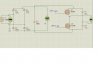
my ques is that .. Where Should i Place Dc Ground ??? in AC Ground ????
here is the Diagram ....
can u Tell me This is right or not ???
The AC ground is determined by the power line. You can connect the safety AC ground (3rd prong) to the equipment chassis if desired. Do not connect the AC neutral to anything but the diodes (the GND connection you show).
The DC common of the rectifier output should not be connected to anything but circuit common for the MOSFET driver circuits. It must remain isolated from the mains ground. If the MOSFETs are driving a transformer with isolated secondaries, then the secondary common can go to the safety ground if desired, but is not required.
means my preceding diagram is right ???
and can i Connect he Common of Triggering circiut to DC ground ???
Can u crutschow Plz draw a Correct Diagram By seeing the Preceding diagram
Still Confused !!!
Can Any one Plz Give a Diagram Of half brigde high freq Inverter
with 220V Ac .....Rectified to Dc And than Connected to MOSFETS ????
Depends upon where that ground connection you show is attached. If it's not connected to anything else you are ok.
Yes you can connect the common of the trigger circuit to DC ground. But that "ground" is live due to the connection to the mains power so it is dangerous to touch. We emphasize that point since you seem to have only a hazy understanding of common and grounds.
You had it correct in the first drawing. DC ground is right where you pointed. In the AC world, "ground" is a safety aspect not a current carrying conductor. The 'ground' or third prong of the plug is connected to the chassis as crutschow mentioned. AC has HOT and NEUTRAL, and for the purposes in this circuit, doesn't matter which is which.
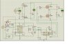
In your last drawing, GND is in the wrong place. You had it right in drawing #1 and then changed it to be wrong in drawing #2.
On post 24:
V1 is the power line. Remove the GND. That is ground for the 'power line' and not for the rest of the parts.
Add GND at Q2-s. You have U12 and U1 connected to GND and Q2-s not connected to GND. If U1 drives Q2 then Q2-S must connect to U1!.
I usually do not have a power line. I would start off by removing V1, D1-4. and add a DC supply form Q2-d to Q1-s. In your case the power line has confused things.
This site uses cookies to help personalise content, tailor your experience and to keep you logged in if you register.
By continuing to use this site, you are consenting to our use of cookies.


")