Continue to Site

Welcome to our site!

Electro Tech is an online community (with over 170,000 members) who enjoy talking about and building electronic circuits, projects and gadgets. To participate you need to register. Registration is free. Click here to register now.

  • Welcome to our site! Electro Tech is an online community (with over 170,000 members) who enjoy talking about and building electronic circuits, projects and gadgets. To participate you need to register. Registration is free. Click here to register now.

AC Coupling Mic to MP3 Output

Status
Not open for further replies.
Howdy!

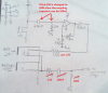
here's a question I'd like a second opinion or angle on. I'm working on a for fun audio project, and here's what I'm looking to do. I want to allow audio from a PC/MP3 player, etc. to be fed into my project as a second option to a microphone built in the circuit. I would prefer to use a switch built into the audio jack to select between the two, as shown below:
Mic_coupling_zpsqjpfts8z.jpg


In the case where the user has their MP3 player in the second jack and nothing plugged into the first to break the circuit, the MP3 player's output is AC coupled to the Mic.

Would this cause any damage to either the MP3 player or Mic?

Should I add a limiting resistor between the audio jacks and microphone, or look for a different solution for selecting between two audio sources to my project?

-EF
 
It would help (yourself ) to define the source impedance and max level for each input, then to balance them, you will see how much R padding to insert. Presumeable the mic input is determined by R drain and that load affects gain. Generally active devices do not tolerate reverse currents outside supply rails but with pads, some isolation is possible from switched cap voltages. Usually an inverting OA mixer is used.

Beware of CM noise from SMPS grounded charger powered sources for noise ingress.
 
Chances are that the mic level is a hundred times less than the mp3 level....
 
Yes, you need a mic preamp with a voltage gain of about 100 times then a mixer circuit.
 
All, thank-you for the input!

This is is what I've found from a different forum:
"
General specs for input/output of Creative Soundcards:
...
> Line-Out:
>
> 0 to 2V RMS or peak to peak.
> Normal output level about 1V.
> Impedance assumed 10K Ohms, some cards 600 Ohms.
> Described as: Given a full Sine wave at 1Khz tone
> and a 10K Ohm > Load should produce about 1V RMS
> output.
"
**broken link removed**

I'm going to keep looking though, that source impedance seems kinda high........


I completely agree that the mic level will be significantly less than the MP3 player. Immediately downstream I was planning on having several op-amp circuits to gain and filter the signal, controlled by a micro.

I don't intend for it to normally operate with two sources at the same time, but rather am trying to avoid any chance of one of the sources damaging the other, or other components, etc. for example, WC both are tied together, and the circuit is in a loud room, the MP3 player set to max volume...

I do like the idea of keeping one op-amp solely for the mic, pulling the signal away from supply noise.

How's this second. drawing. If I understand correctly, I want Rpad to be >= then that of the Audio source/MP3's output impedance?
Circuit2_zpsh3fx45pb.jpg


-EF
 
Few low noise audio opamps work from a power supply voltage as low as only 5V and if you find one then it will cause severe clipping distortion for sounds louder than normal because it has almost no "headroom". Use a supply of at least 9V.
Your opamp amplifies DC so its bias will be affected by its amplified DC input offset voltage. You should add a capacitor to ground in series with the resistor from its (-) input and the wrong 2.5V connection so that it has a DC gain of 1.
 
Why is bottom jack hardwired to mic output? Is that an output? or bidirectional?
 
Thankyou for the input fellas!


Few low noise audio opamps work from a power supply voltage as low as only 5V and if you find one then it will cause severe clipping distortion for sounds louder than normal because it has almost no "headroom". Use a supply of at least 9V.
Your opamp amplifies DC so its bias will be affected by its amplified DC input offset voltage. You should add a capacitor to ground in series with the resistor from its (-) input and the wrong 2.5V connection so that it has a DC gain of 1.

Understood, gosh, I don't know why I didn't see that, but it makes sense to help keep the DC from being amplified. Thank-you!

Why is bottom jack hardwired to mic output? Is that an output? or bidirectional?

The bottom two jacks are tied together to allow a "passthrough" (if that's the right term for it) so if using an MP3 player, the original signal can continue on its way to a stereo/etc. I am using a switch built in in the first jack to break the Mic's connection when the MP3 source is plugged in.


Alright,

Added in values, as well as a "pad" resistor on the "Audio in" as well. Look at Vs as a static value at 9VDC
Circuit4_zpsvtzjvvqz.jpg

Looking primarily at where the two sources will meet, will this potentially create an issue/problem?

I understand that last resistor in the signal path creates that un-desirable divider. Heheh, next problem to solve, along with tweaking values on my discretes, Quick selection by hand, I'm sure they are far from perfect...

-EF
 
With 22k series resistors then the peak short circuit current from the opamp is only 3.5V/22k=0.16mA which is nothing since most opamps limit their max output current to at least 10mA, use 1.5k for a peak current of 2.3mA and much less attenuation.
 

Attachments

  • mic preamp.png
    mic preamp.png
    429.1 KB · Views: 135
Status
Not open for further replies.

Latest threads

New Articles From Microcontroller Tips

Back
Top