Continue to Site

Welcome to our site!

Electro Tech is an online community (with over 170,000 members) who enjoy talking about and building electronic circuits, projects and gadgets. To participate you need to register. Registration is free. Click here to register now.

  • Welcome to our site! Electro Tech is an online community (with over 170,000 members) who enjoy talking about and building electronic circuits, projects and gadgets. To participate you need to register. Registration is free. Click here to register now.

Absolute Circuit with op-amp OP07CP

Status
Not open for further replies.

Minh Thanh

New Member
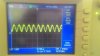
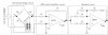
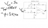
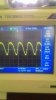
Hi Guys, As I knew : Vout of Absolute circuit must be FUll WAVE and Vout 's Frequence is equal to Vin is 5Khz. But real result is wrong ,you can see three of pictures that I have attached in below and give me your opinion, please Thanks you !
 

Attachments

  • ABSOLUTE.PNG
    ABSOLUTE.PNG
    32.2 KB · Views: 158
  • RESULT OF ABSOLUTE CIRCUIT.jpg
    RESULT OF ABSOLUTE CIRCUIT.jpg
    104.3 KB · Views: 153
  • EC CIRCUIT.PNG
    EC CIRCUIT.PNG
    47 KB · Views: 138
Last edited:
somewhat related **broken link removed**
from "homestead"
https://www.electro-tech-online.com...-to-measure-short-signals-from-a-piezo.88275/
————————
the LFxxx OpAmp seems to start working somewhat from ±6V (12V TOT) supply !!! applies to buffer for Vin = (Vdd - Vss)·(1/2)·(1 ± 1/2) !!!
your thing (as on .PNG)
Random_139_V010.png -- it does not like much frequency at this input amplitude , there's still some phase-shift detectable for bare eye at 5kHz/256 = 19.5Hz
————————
some alternates ::
Random_139_0010.png
 
Last edited:
Why does the 'scope show an output frequency of only 50.3Hz? Then its input frequency must be 25.15Hz
 
Looks like you are picking up 50Hz main's noise.

What are the op amp supply voltages?

That's a poor absolute value circuit as the two input diodes are not in a feedback loop and thus attenuate the input.
With that design you need at least 500mVrms to get any output.
Suggest you look for "precision" full-wave rectifier circuits.
Supply voltage : +/- 9v.... I am measuring Electrical Conductivity of Solution so Vin is either positive or negative. Could you see attached file below ? That is EC circuit and Give me your opinion , please .
 

Attachments

  • EC CIRCUIT.PNG
    EC CIRCUIT.PNG
    47 KB · Views: 145
The opamp circuits in your design have no voltage gain and the diodes attenuate the signal so the sensitivity will be very low.
 
That is EC circuit and Give me your opinion , please .
As I stated, for that absolute value circuit you need at least 1.4Vpp signal at it's input so you will either need to go to a better absolute value circuit, such as ron showed in post #7, or you need to add gain in the differential circuit by changing the feedback resistor and the resistor to ground to a higher value.

I recommend you go with ron's circuit, as the one you have is not a good design.
Below is the LTspice simulation of that circuit:

upload_2017-7-18_21-1-22.png
 

Attachments

  • Precision Full Wave Rectifier Dual Supply.asc
    2.2 KB · Views: 95
i hope you have regulated and balanced supply for that + & - 9V
-- ??? perhaps there'd be some advance to decouple your excitation supply by in series capacitor ~AC ø—̟|]–̠- ⃟ —► ← ignore this suggestion !!! incase you do not have 'anomalous' output
 
i hope you have regulated and balanced supply for that + & - 9V...

Since there are no bias voltages derived directly from the +V and/or -V, and any modern opamps have a Power Supply Rejection Ratio (PSRR) of ~100db, why would the supplies need to be regulated???
 
run a simulation . . . or accept greater/more undefined error range for your measurement result
. . .
noisy and/or usteady supply also contributes to the instability of an amplifier circuit ... the stabilizing of what may turn out greater / more expensive challenge than simply setting your supply firm
. . .
it is to avoid known issues from the beginning not starting capturing up the way around back to forth - later when they arrive

? whats the use of high PSRR value :
cc_Draft_PSRR.png
 
Last edited:
Although it is "working", I would still use Ron's circuit.

The circuit that you have shown has two diodes outside the feedback loop, and utilizes a third one in the feedback loop in a feeble attempt to compensate for that.

Unless all three diode currents are perfectly matched, which are not since the impedance looking at V(+) is different from that of V(-), you will get the artifacts that you show in your scope waveforms.
 
whats the use of high PSRR value :
It shows the rejection of power supply variations to the output of the op amp.
It's why you normally don't worry about power supply voltage stability when using op amps.
If you don't know that, then why do you think you know enough to tell others how to use them? :confused:
 
i guess it goes ok with me that far
i also don't give a sh¡t how you run your circuitry
Well that's fair because I really don't care if you give a sh*t or not. :angelic:
Just stay off these forums if you don't know what you are talking about.
 
Status
Not open for further replies.

Latest threads

New Articles From Microcontroller Tips

Back
Top