Yes, it was wrong to drive negative voltages into the input pin of the second opamp. It might work for one minute or work for one hour before it is destroyed.
Yes, so that it can safely feed only positive voltages into the input in of the second opamp.
Yes, it creates a very low impedance for the DC power. All electronic circuits should have a supply bypass capacitor at the circuit to prevent oscillations and remove hum.
No, I removed the AC coupling capacitor and the 0V biasing resistor, they were not used as a filter. The capacitor blocked the 4.5VDC from the first opamp so that the second opamp could turn off the LEDs when there is no signal.
You do not understand that my new direct connection from the output of the first opamp to the input of the second opamp passes AC and DC.
The coupling capacitor that I removed blocked the +4.5V DC bias of the first opamp but passed AC. It was needed so that the input of the second opamp could be biased at 0V so that the LEDs could turn off when there was no sound and the AC was the positive parts of the audio to turn on the LEDs.
No, the RC was not a filter.
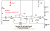
The simple circuit needs to amplify only the positive parts of the signal. The LM358 does this perfectly when its input is biased at 0V and when the input signal never goes negative more than 0.3V (the mic signal is about 0.02V). Its gain is the same as when it is biased at +4.5V. The gain of the first opamp is 470k/(2.2k + the 2.7k output impedance of the mic)= about 68 times. The second opamp has no gain, the output current level of the transistor is the same as the input voltage level to the second opamp.