Electro Tech is an online community (with over 170,000 members) who enjoy talking about and building electronic circuits, projects and gadgets. To participate you need to register. Registration is free. Click here to register now.
Welcome to our site! Electro Tech is an online community (with over 170,000 members) who enjoy talking about and building electronic circuits, projects and gadgets. To participate you need to register. Registration is free. Click here to register now.
Hi.
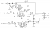
I find a very strange circuit (gate operator) diagram.
Can any one have any clue how this 7805 work in this very strange application?
Or maybe there is a error in the diagram.
@tcmtech, That was my first impression too. Spent the last hour trying to find another example on Google to no avail. That regulator does have 100 mA internal current limiting. I looked at it as a limiter rather than a current regulator , which typically has a resistor from output to ground.
The output is connected to ground.
So essentially, they are using the regulator's self-limiting output current feature, to act as current limiter for the load.
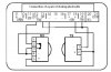
I'm not sure that this LTSpice model for the LM7805 faithfully behaves correctly when the output pin is shorted to ground, but here is what a sim shows for the voltage vs current. I know that the modelling is not realistic for input currents in excess of ~500mA because the chip would go into a self-protecting thermal shutdown mode.
The loads connected suggest that the 7805 are being used as some sort of voltage clamp during lightning. Since this is a gate operator, that might be the case.
I suspect most of you are familiar with Horowitz and Hill's popular, but now very old, textbook (1989). That circuit is the sort of thing I expected to see in "good ideas" or "bad ideas." It is in neither. Just FYI. I hope the OP will tell us where he got it.
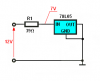
I decided to test this circuit on the breadboarded.
I use 12V power supply and 78L05 in TO-92 package.
And for low current, below 100mA nothing interesting really happens. The voltage drop across LM is between 1.4V and 2V, depending on current flow.
Interesting things start to happen when we increase the current above 100mA. The power dissipation in the circuit also increase and LM move into "thermal protection mode". Limited the current so that the power dissipation is not increased above Ptot = (Tj - Ta)/Rthja.
For example for this circuit. At the beginning the current was equal to 0.22A. But after some period of time circuit reaches thermal equilibrium. And current drops to 0.13A and voltage drop across LM is around 7V. So for thermal condition in my room Ptot _max = 0.84W.
But if this type of a circuit is really necessary in this specified application?
In your original post, you ask rhetorically whether there might be an error in the diagram. Have you confirmed by direct examination that there is no resistor from the output of the 7805's to ground?
I wrote the American company, which referred me to its technical service in Florida. Those phones were out of order until early this afternoon (03.26.13 EDT USA). The person I spoke with in Florida gave me the email address of the company in Ireland that actually designed and produces the boards. I contacted that company and am awaiting a response.
I think Mr. RB has is right. It looks like they are really concerned with over current as they protected the top circuit as well. May just be a poor mans current limiter.
I think Mr. RB has is right. It looks like they are really concerned with over current as they protected the top circuit as well. May just be a poor mans current limiter.
Doesn't "current limiter" imply something that limits current that flows though it? This is used to shunt current to ground, therefore it is a "voltage limiter".`
Sorry Mike you have misread the schematic. They are placed in series between the collector of the output switch device, and the output pin. (The pins on the 7805 are labelled "GND" but do not actually connect to circuit ground).
It looks to be fault current limiting to me and it's not atypical in some commercial devices.
This site uses cookies to help personalise content, tailor your experience and to keep you logged in if you register.
By continuing to use this site, you are consenting to our use of cookies.