We can express this in English as "Less is More"or do you maybe no even better examples how "to much isn't always more" ?
An example from the past week:
A few months ago a bought a new "hobby car", a Mazda MX5 to be precise.
The car is eight years old, and one of the previous owners has replaced the OEM radio with some aftermarket wonder, probably because the new radio has a USB port for an iPod type thing.
When it comes to in car entertainment, I am a simple soul and just want to listen to a couple of stations, and if they do not have something which interests me, I will switch off and just drive the car.
Here is the problem, the new radio is incompatible with the radio controls which are built in to the car steering wheel.
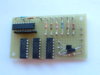
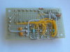
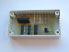
Having eventually found the information which describes the output from the steering wheel and what the radio expects, I was able to make a little converter so that I can use my steering wheel controls. And it works well.
The controls on the aftermarket radio are an ergonomic nightmare.
The rotary control is quite thin and difficult for my large fingers to grip.
If the rotary control is pushed, it takes you off into some setup mode. You get out of the setup mode by pushing on another tiny button.
All the push buttons for preset stations and other odd functions are tiny and close together.
How the HELL are you supposed to simply change stations or set the volume UP/DOWN as you drive down the road?
One really useful (yeah right!) feature of this aftermarket radio is that you can select the colour of the illumination of the frontpanel controls!
WHAT!
I need a feature like that like I need a hole in the top of my head!
So as far as I am concerned KISS - Keep It Simple Stupid
JimB