Hello again,
Since the current is 90 degrees out of phase with the voltage in the inductor, that means the resistor current is 90 degrees out of phase with the voltage in the inductor, so that means the voltage across the resistor is 90 degrees out of phase with the inductor voltage.
But when the line voltage goes to zero (twice per cycle) the inductor still contains energy, and the resistor is dissipating power. Therefore the resistor gets it power from the inductor alone during that brief period, and after which it would get it's power from the inductor and the line.
I think it might help to do two things here:
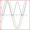
1. Plot the energy stored in the inductor (not i(v)*vL(L) which is different). The energy is (1/2)*L*i^2 and is always positive.
2. Start with the initial inductor current of zero as before, but this time look at the waveform after 5 time constants, which would be 50ms, but to sync with the line period start looking at 60ms. A good time to view is between 60ms and 80ms. This ensures that all transient phenomena have died out.
3. Plot the resistor power.
4. Try to look at times when something goes through zero. When something goes through zero that eliminates that as a contribution to the circuit because a zero voltage can not deliver nor absorb power for example.
If the line is supplied with energy and you dont have anything else plugged in, then you are now supplying the neighbors with energy
")
This is in fact a key point with solar powered line tied inverters that are used to convert solar energy into electrical energy and pump it into the line. There we do it on purpose, but with the inductor resistor circuit it's just natural. So the line itself does not absorb the bulk of the energy but another load somewhere else would absorb that energy. There is some energy absorbed in the line itself however because the line wires are not perfect conductors so the conductors themselves dissipate energy as heat in the process of delivering the energy to another load.
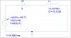
You can look at this as the two battery circuit you mentioned, but instead of connecting them directly in parallel connect them with a small resistor in series with the positive terminals. When one battery is 3.0v and the other 3.0v no current flows between the batteries and thus no current through the resistor. But when one is 3v and the other 1.5v then there is a potential difference of 1.5v across the resistor so current flows from the 3v batt to the 1.5v batt, thus attempting to charge the 1.5v batt. But if the 1.5v batt also had a load resistor across it, the load resistor would absorb some of that energy so the battery would not charge as much. Note also that if the 1.5v batt had a large series resistance inside of it, the terminal voltage would go up to almost 3 volts. If this happened in the line/inductor/resistor circuit the line voltage could shoot up to a much higher value ruining other equipment plugged into the line.