Heidi
Member
Dear friends,
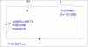
In a circuit in which an AC source, R,L are connected in series, the average/real/active power delivered to combination of R and L is, according to its definition, the average of product of the instantaneous source voltage and the source current in one period of the instantaneous source voltage/current.
Is it correct that the average power can also be obtained by calculating the average of product of the instantaneous voltage across the RESISTOR and the current through the RESISTOR in one period?
Thank you!
")

