Continue to Site

Welcome to our site!

Electro Tech is an online community (with over 170,000 members) who enjoy talking about and building electronic circuits, projects and gadgets. To participate you need to register. Registration is free. Click here to register now.

  • Welcome to our site! Electro Tech is an online community (with over 170,000 members) who enjoy talking about and building electronic circuits, projects and gadgets. To participate you need to register. Registration is free. Click here to register now.

A question about Nigel Goodwin's tutorials

Status
Not open for further replies.

aljamri

Member
Hi everybody,

I am doing Nigel Goodwin's tutorials. Finished LED tutorials, and started Switches tutorial. I faced a problem and spent last week revising my work for any clear mistake. It repated itself in all the three tutorials 2.1, 2.2, and 2.3.

One of the switches and the corresponding LED turns ON whenever I switch on the power and makes no any response.

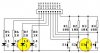
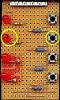
Attached Nigel's board on which I marked the Switch and LED. And this is the tutorial's link


and here is the first tutorial code where I added A into the list and config files since I am using PIC16F628A.


Code:
;Tutorial 2.1 - Nigel Goodwin 2002
	LIST	p=16F628A		;tell assembler what chip we are using
	include "P16F628A.inc"		;include the defaults for the chip
	__config 0x3D18			;sets the configuration settings (oscillator type etc.)


LEDPORT	Equ	PORTA			;set constant LEDPORT = 'PORTA'
SWPORT	Equ	PORTA			;set constant SWPORT = 'PORTA'
LEDTRIS	Equ	TRISA			;set constant for TRIS register
SW1	Equ	7			;set constants for the switches
SW2	Equ	6
SW3	Equ	5
SW4	Equ	4
LED1	Equ	3			;and for the LED's
LED2	Equ	2
LED3	Equ	1
LED4	Equ	0

;end of defines
	
	org	0x0000			;org sets the origin, 0x0000 for the 16F628,
					;this is where the program starts running	
	movlw	0x07
	movwf	CMCON			;turn comparators off (make it like a 16F84)

   	bsf 	STATUS,		RP0	;select bank 1
   	movlw 	b'11110000'		;set PortA 4 inputs, 4 outputs
   	movwf 	LEDTRIS
	bcf	STATUS,		RP0	;select bank 0
	clrf	LEDPORT			;set all outputs low


Loop	btfss	SWPORT,	SW1
	call	Switch1
	btfss	SWPORT,	SW2
	call	Switch2
	btfss	SWPORT,	SW3
	call	Switch3
	btfss	SWPORT,	SW4
	call	Switch4
	goto	Loop

Switch1	clrf	LEDPORT			;turn all LED's off
	bsf	SWPORT,	LED1		;turn LED1 on
	retlw	0x00

Switch2	clrf	LEDPORT			;turn all LED's off
	bsf	SWPORT,	LED2		;turn LED2 on
	retlw	0x00

Switch3	clrf	LEDPORT			;turn all LED's off
	bsf	SWPORT,	LED3		;turn LED3 on
	retlw	0x00

Switch4	clrf	LEDPORT			;turn all LED's off
	bsf	SWPORT,	LED4		;turn LED4 on
	retlw	0x00


	end

can any one tell me where I made mistake?

Thanks
 

Attachments

  • 1.JPG
    1.JPG
    21.9 KB · Views: 226
  • 2.JPG
    2.JPG
    21.4 KB · Views: 206
The code seems fine... I suspect a hardware fault that is a short with probably accidentaly grounded the respective switch port and check the switch?

or try this code and see if the same led still goes off...

Code:
;Tutorial 2.1 - Nigel Goodwin 2002
	LIST	p=16F628A		;tell assembler what chip we are using
	include "P16F628A.inc"		;include the defaults for the chip
	__config 0x3D18			;sets the configuration settings (oscillator type etc.)


LEDPORT	Equ	PORTA			;set constant LEDPORT = 'PORTA'
SWPORT	Equ	PORTA			;set constant SWPORT = 'PORTA'
LEDTRIS	Equ	TRISA			;set constant for TRIS register
SW1	Equ	7			;set constants for the switches
SW2	Equ	6
SW3	Equ	5
SW4	Equ	4
LED1	Equ	3			;and for the LED's
LED2	Equ	2
LED3	Equ	1
LED4	Equ	0

;end of defines
	
	org	0x0000			;org sets the origin, 0x0000 for the 16F628,
					;this is where the program starts running	
	movlw	0x07
	movwf	CMCON			;turn comparators off (make it like a 16F84)

   	bsf 	STATUS,		RP0	;select bank 1
   	movlw 	b'11110000'		;set PortA 4 inputs, 4 outputs
   	movwf 	LEDTRIS
	bcf	STATUS,		RP0	;select bank 0
	clrf	LEDPORT			;set all outputs low


Loop	btfss	SWPORT,	SW1
	call	Switch1
	btfss	SWPORT,	SW2
	call	Switch2
	btfss	SWPORT,	SW3
	call	Switch3
	btfss	SWPORT,	SW4
	call	Switch4
	goto	Loop

Switch1	clrf	LEDPORT			;turn all LED's off
	bsf	SWPORT,	LED1		;turn LED1 on
	retlw	0x00

Switch2	clrf	LEDPORT			;changed the two
	bsf	SWPORT,	LED3		;Led sequence, see if
	retlw	0x00			;it still lights up the same.
 					;if it lights up the other
Switch3	clrf	LEDPORT			;LED, then it is the switch
	bsf	SWPORT,	LED2		;having problem or a short.
	retlw	0x00

Switch4	clrf	LEDPORT			;turn all LED's off
	bsf	SWPORT,	LED4		;turn LED4 on
	retlw	0x00


	end
 
Last edited:
Nigel Goodwin said:
If you're using an A series chip, you need to alter the config line from 0x3D18 to 0x2118

One more time you are CORRECT. I replaced it and it is working fine.


skyrock said:
or try this code and see if the same led still goes off...

I tried it and got the same problem which shows a software mistake.


thanks for all
 
another question please:

in the following part of the program, where dose retlw 0x00 command will return ? and can i decied to retrun into another part?


Code:
Loop	btfss	SWPORT,	SW1
	call	Switch1
	btfss	SWPORT,	SW2
	call	Switch2
	btfss	SWPORT,	SW3
	call	Switch3
	btfss	SWPORT,	SW4
	call	Switch4
	goto	Loop

Switch1	clrf	LEDPORT			;turn all LED's off
	bsf	SWPORT,	LED1		;turn LED1 on
	[COLOR="Red"]retlw	0x00[/COLOR]
 
aljamri said:
One more time you are CORRECT. I replaced it and it is working fine.
thanks for all

hi aljamri,
I am a little puzzzled why the change of CONFIG from 0x3D18 to 0x2118 cleared the problem , as bits 12 to 9 in the CONFIG WORD are read as Zero's anyway.[they are ignored if Set]

So 0x3D18 should have the same effect as 0x2118.???

Am I missing something.?:confused:

BTW: the original program works OK in my system.
 
aljamri said:
another question please:

in the following part of the program, where dose retlw 0x00 command will return ? and can i decied to retrun into another part?


Code:
Loop	btfss	SWPORT,	SW1
	[COLOR="Red"]call	Switch1[/COLOR]
	[COLOR="Blue"]btfss	SWPORT,	SW2[/COLOR]
	call	Switch2
	btfss	SWPORT,	SW3
	call	Switch3
	btfss	SWPORT,	SW4
	[COLOR="SeaGreen"]goto Switch4[/COLOR];;call	Switch4
	goto	Loop

Switch1	clrf	LEDPORT			;turn all LED's off
	bsf	SWPORT,	LED1		;turn LED1 on
	[COLOR="Red"]retlw	0x00[/COLOR]

Switch4	clrf	LEDPORT			;turn all LED's off
	bsf	SWPORT,	LED1		;turn LED1 on
	[COLOR="seagreen"]goto some_where[/COLOR];;;[COLOR="Red"]retlw	0x00[/COLOR]

hi,
This would return you to the next line after the CALL, ready for the next bit test.

and can i decied to retrun into another part?

The simple way would be to replace the CALL with a GOTO and when you exit the routine that the GOTO took you too, you juts use another GOTO, not a RETURN.

OK.?
 
Last edited:
ericgibbs said:
hi aljamri,
I am a little puzzzled why the change of CONFIG from 0x3D18 to 0x2118 cleared the problem , as bits 12 to 9 in the CONFIG WORD are read as Zero's anyway.[they are ignored if Set]

So 0x3D18 should have the same effect as 0x2118.???

Am I missing something.?:confused:

I noticed that the type of Oscillator has changed and everything became fine.
 
ericgibbs said:
hi,
This would return you to the next line after the CALL, ready for the next bit test.


The simple way would be to replace the CALL with a GOTO and when you exit the routine that the GOTO took you too, you juts use another GOTO, not a RETURN.

OK.?


Thanks for your reply. what i am trying to do is just like some digital devices where they used a single button for many functions, you simply press the same button for a longer period to go for another option.

I manipulated Nigle's program as follows:

Code:
1   Loop    btfss   SWPORT,SW1	        ; test sw1 pressed ?
2	    call    Switch1		; if not gosub to Switch1
3	    call    Delay		; call Delay &come to next line
4	    btfss  SWPORT,SW1	        ; Is sw1 still pressed
5	    call    Switch2	        ; If yes gosub to Switch2
6	    goto	Loop               ; or do loop again
7
8 Switch1   clrf    LEDPORT			
9	     bsf     SWPORT,LED1		
10	     retlw   0x00		; to which line it'l return? 
11					
12 Switch2   clrf    LEDPORT			
13	     bsf     SWPORT,LED3		
14	     retlw   0x00			
15
16
17 Delay


Is this correct ?
 
Code:
1   Loop    btfss   SWPORT,SW1	        ; test sw1 pressed ?
2	    call    Switch1		; if not gosub to Switch1
3	    call    Delay		; call Delay &come to next line
4	    btfss  SWPORT,SW1	        ; Is sw1 still pressed
5	    call    Switch2	        ; If yes gosub to Switch2
6	    goto	Loop               ; or do loop again

hi,
Wont this always execute the CALL Switch1.?

Consider you have pushed switch #1 so you goto the Switch #1 subr, then you test the switch again, after a delay, while you are still in the SW#1 subr.
If still pressed after the delay,do something.....if not pressed at the of the delay do something else....

Take care regarding switch bounce.
 
Last edited:
ericgibbs said:
Code:
1   Loop    btfss   SWPORT,SW1	        ; test sw1 pressed ?
2	    call    Switch1		; if not gosub to Switch1
3	    call    Delay		; call Delay &come to next line
4	    btfss  SWPORT,SW1	        ; Is sw1 still pressed
5	    call    Switch2	        ; If yes gosub to Switch2
6	    goto	Loop               ; or do loop again

hi,
Wont this always execute the CALL Switch1.?.

Yes that is the sitiuation when I run the code LED1 is always ON


ericgibbs said:
Consider you have pushed switch #1 so you goto the Switch #1 subr, then you test the switch again, after a delay, while you are still in the SW#1 subr.
If still pressed after the delay,do something.....if not pressed at the of the delay do something else.....

That is what i am looking for, so that i want retlw to go for line 3 after completing Switch1 subroutin.

ericgibbs said:
Take care regarding switch bounce.

that is waht i'm afraid of. Nigle has a debouncy routin i'll try to insert it in between.

thanks for your time share.
 
hi,
Can you post photo's of the pcb you have made, front and back.

That Sw1 should not Call subr1 unless the Sw#1 is pressed, you must have a hardware fault, lets look at your pcb.

To jump from routine to routine, its easier to use the GOTO rather than CALL while you are debugging.
 
Sorry Eric, may be i missleaded you.

the original program run verywell, Nigle's suggestion to change Config word solved my problem.

Now I'm trying to modify the code to do what i've stated using only one switch to get two different options, only by entering a delay in press as follows:

* When SW1 pressed (instantnusly), LED1 ON
* If SW1 still pressed after 5sec, LED2 ON

This idea used in many digital instruments.

Sorry again for missleading you


*
 
aljamri said:
Sorry Eric, may be i missleaded you.

the original program run verywell, Nigle's suggestion to change Config word solved my problem.

Now I'm trying to modify the code to do what i've stated using only one switch to get two different options, only by entering a delay in press as follows:

* When SW1 pressed (instantnusly), LED1 ON
* If SW1 still pressed after 5sec, LED2 ON

This idea used in many digital instruments.

Sorry again for missleading you


*
hi,
No problem.

Have you considered this method:
Push Sw#1 .... do something and test for

Push Sw#2 to #4, while Push Sw#1 is still pressed
If its Sw#2 then do something 22222
If its Sw#3 then do something 33333
If its Sw#4 then do something 44444

Push Sw#2... do test for Sw#3 or Sw#4

No user Delay states.

Do you follow this.?
 
aljamri said:
Sorry Eric, may be i missleaded you.

the original program run verywell, Nigle's suggestion to change Config word solved my problem.

Now I'm trying to modify the code to do what i've stated using only one switch to get two different options, only by entering a delay in press as follows:

* When SW1 pressed (instantnusly), LED1 ON
* If SW1 still pressed after 5sec, LED2 ON

This idea used in many digital instruments.

Sorry again for missleading you


*
What you normally want to do for something like this is only take action when the switch is released. That way you can time how long the switch is down and when it is released you can use that time to determine the appropriate action to take.

Mike
 
ericgibbs said:
hi,
No problem.

Have you considered this method:
Push Sw#1 .... do something and test for

Push Sw#2 to #4, while Push Sw#1 is still pressed
If its Sw#2 then do something 22222
If its Sw#3 then do something 33333
If its Sw#4 then do something 44444

Push Sw#2... do test for Sw#3 or Sw#4

No user Delay states.

Do you follow this.?


i'm trying to save i/o's by using one switch for more than one function.
 
i'm trying to save i/o's by using one switch for more than one
function.

You would save pins doing it this way.

Have you also considered using one or more analog inputs connected to a resistive divider chain connected between +5V and 0V.?

It would be possible to connect about 8 or 10 switches to one analog input.
The voltage level at the ADC input could be checked to see which Sw has been pushed.
 
ericgibbs said:
You would save pins doing it this way.

Have you also considered using one or more analog inputs connected to a resistive divider chain connected between +5V and 0V.?

It would be possible to connect about 8 or 10 switches to one analog input.
The voltage level at the ADC input could be checked to see which Sw has been pushed.

ADC and display tutorials are my target for my next project. I'll try to do LCD panel indicator with 1-5 volts input ( 4 - 20 mA ). I want to use it to give indication for Level, Flow, Conductivity and many others.
 
Detecting and processing "short" and "long" switch presses as Mike (Pommie) pointed out often requires detecting both the new press and the new release portion of the switch cycle. A switch state 'latch' or 'memory' makes the process much easier.

In operation you would press the switch and hear a single beep. If you release the button before 2 seconds your program will find a '1' in the SwFlags variable. If on the other hand you continue to hold the switch you'll hear a double-beep after 2 seconds and when you release the switch you'll find a '1' in the SwLong variable.

Code:
;
;  interrupts at 1 msec intervals
;
;  dec(Tmr10)                           '
;  if(Tmr10 = 0)                        ' if 10 msec interval
;    Tmr10 = 10                         ' reset 10 msec counter
;
;    SwState = PORTB ^ 255              ' invert active low switches
;    SwState = SwState & 1              ' mask for switch on RB0
;    Changed = SwState ^ SwLatch        ' changed (press or release)
;    NewPress = Changed & SwState       ' a 'new' switch press
;    NewRelease = Changed & SwLatch     ' a 'new' switch release
;    SwLatch = SwState                  ' update switch state latch
;
;    if(Tmr2000 > 0) then               ' if 2 sec timer running
;      dec(Tmr2000)                     ' decrement timer
;      if(Tmr2000 = 0) then             ' if 2 sec time-out
;        Beep = 4                       ' task double beep feedback
;      endif                            '
;    endif                              '
;
;    if(NewPress > 0) then              ' if new switch 'press'
;      Beep = 2                         ' task a single beep and
;      Tmr2000 = 200                    ' start 2 second timer
;    endif                              ' (200 x 10 msecs)
;
;    if(NewRelease > 0) then            ' if new switch 'release'
;      SwLong = SwLong ^ NewRelease     ' set 'long' switch flag
;      if(Tmr2000 > 0) then             ' if less than 2 seconds
;        SwLong = SwLong ^ NewRelease   ' clr 'long' switch flag
;        SwFlags = SwFlags ^ NewRelease ' set 'short' switch flag
;        Tmr2000 = 0                    ' clear 2 second timer
;      endif
;    endif
;  endif
;
BeepTask
        movf    Beep,F          ; beep enabled?                   |B0
        bz      KeyProc         ; no, branch, else                |B0
        movf    PORTB,W         ; W = PORTB image                 |B0
        xorlw   b'10000000'     ; toggle spkr bit (b7)            |B0
        btfss   Beep,0          ; b0 = 1? yes, skip, else         |B0
        movwf   PORTB           ; toggle spkr pin (RB7)           |B0
        decfsz  Bctr,F          ; dec 32 msec counter             |B0
        goto    KeyProc         ;                                 |B0
        decf    Beep,F          ; decrement Beep                  |B0
        bsf     Bctr,5          ; reset 32 msec counter           |B0
KeyProc
        decfsz  Tmr10,F         ; 10 msec interval?               |B0
        goto    ISRexit         ; no, branch, else                |B0
        movlw   10              ; reset 10 msec counter           |B0
        movwf   Tmr10           ;                                 |B0
KeyTimer
        movf    Tmr2000,F       ; is 2 second timer running?      |B0
        bz      KeyPress        ; no, branch, else                |B0
        decf    Tmr2000,F       ; dec timer. 2 seconds elapsed?   |B0
        skpnz                   ; no, skip, else                  |B0
        bsf     Beep,2          ; task double beep feedback       |B0
KeyPress
        comf    PORTB,W         ; get current active low switch   |B0
        andlw   b'00000001'     ; mask for switch on RB0          |B0
        movwf   SwState         ; save current switch state       |B0
        xorwf   SwLatch,W       ; W = changes (press or release)  |B0
        andwf   SwState,W       ; a new switch "press"?           |B0
        bz      KeyRelease      ; no, branch, else                |B0
        bsf     Beep,1          ; task single "new press" beep    |B0
        movlw   2000/10         ; start 2 second timer            |B0
        movwf   Tmr2000         ; (2000-msec/10-msec = 100)       |B0
KeyRelease
        movf    SwState,W       ; W = current switch state        |B0
        xorwf   SwLatch,W       ; W = changes (press or release)  |B0
        andwf   SwLatch,W       ; a new switch "release"?         |B0
        bz      KeyUpdate       ; no, branch, else                |B0
        xorwf   SwLong,F        ; set the "long" flag             |B0
        movf    Tmr2000,F       ; timed out 2 second timer?       |B0
        bz      KeyUpdate       ; yes, branch, else               |B0
        xorwf   SwLong,F        ; clr the "long" flag             |B0
        xorwf   SwFlags,F       ; set the "short" flag            |B0
        clrf    Tmr2000         ; clr 2 second timer              |B0
KeyUpdate
        movf    SwState,W       ; W = current switch state        |B0
        movwf   SwLatch         ; update switch state latch       |B0
 
Last edited:
Status
Not open for further replies.

Latest threads

New Articles From Microcontroller Tips

Back
Top