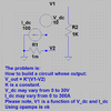
I am very sorry. It seems I wrongly simplified the schematic of the problem above. So just to complete the topic, I attached the updated one below. Now, it looks like the case of a hi-side differential amplifier (though R2 is not a sensor here). Although special ICs are made for hi-side sensors, they may not be suitable for a relatively high voltage on it (here, it is V1-V2 on R2 where V2 is close to ground). Also, I avoid, as possible, using special ICs while I have a lot of conventional opamps.
Anyway, it is up to you now to try sharing your ideas or not about a practical solution. On my side, I am sure
")
I will find one which could be rather simple and suitable for the project I am working on.
Best wishes,
Kerim
View attachment 140254

")
