Continue to Site

Welcome to our site!

Electro Tech is an online community (with over 170,000 members) who enjoy talking about and building electronic circuits, projects and gadgets. To participate you need to register. Registration is free. Click here to register now.

  • Welcome to our site! Electro Tech is an online community (with over 170,000 members) who enjoy talking about and building electronic circuits, projects and gadgets. To participate you need to register. Registration is free. Click here to register now.

Zoodie81

New Member
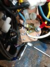
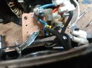
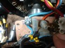
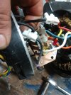
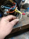
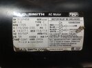
Hi all. I'm having issues with an A.O. Smith 1hp dual voltage reversible capacitor start induction run motor. I'm trying to wire the motor to a run switch for the turntable on a John Bean 8950 tire changer. Someone was messing with it before me and did not mark any wires to the switch and all wires coming out of motor are black. I understand how to wire the switch but I am not sure what wires from the motor are the correct ones to go to the switch. There are 6 wires from the motor that go to a terminal board but only four shown on the wiring diagram. I cannot find a diagram online for this motor. Also a red wire and black wire have been taken off the board and run straight from the windings to the drum switch. The motor is from 1998. A.O. Smith's motor division was night out and this motor discontinued. I'll post pictures. IMG_20231128_032758104.jpgIMG_20231128_042632504.jpgIMG_20231128_042706876.jpgIMG_20231128_042730935.jpgIMG_20231128_042740474.jpgIMG_20231128_032841290.jpgIMG_20231128_032856421.jpg
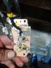
 
Update, I found that the red and black go to the capacitor so I believe those are the start windings and the other 4 wires are the run windings. The numbering on the board though has me confused are the 3 prongs off L2 1,2 and 3 or are the two outermost ones 1 and 2 and number 3 the next post up which has 4 in between it and the orange wire?
 

Latest threads

New Articles From Microcontroller Tips

Back
Top