Continue to Site

Welcome to our site!

Electro Tech is an online community (with over 170,000 members) who enjoy talking about and building electronic circuits, projects and gadgets. To participate you need to register. Registration is free. Click here to register now.

  • Welcome to our site! Electro Tech is an online community (with over 170,000 members) who enjoy talking about and building electronic circuits, projects and gadgets. To participate you need to register. Registration is free. Click here to register now.

A nasty question regarding current shunts.

Status
Not open for further replies.

0mega

New Member
Dear All,

I have run into a bit of a problem. I am using a .1 ohm current shunt which is located between the negative terminal of my battery and the system ground of my application:

0.1 R
0V > ---/\/\/\/\-----------/\/\/\/\--------------- < +12V
|
-----
--
-

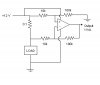
I wish to convert the voltage across the shunt (eg. -200 mV) into a usable analog voltage (eg. 2V). I realize an op-amp can be used, but how? I don't know much about op-amps. I know how to use them to multiply the voltage by 10, but because it is -ve with respect to ground, i am utterly clueless.

Thankyou very much,

John B
 
have a look at diff amp arrangements.
for a gain on x10 you will need a factor of 10 between the resistors

say feedback 10k the feeders 1k

sorry no means to draw and post a cct at the mo otherwise I would
 
It would be easier, if you used the negative battery terminal as your system ground (I assume you have some sort of control system). Is this possible? What is the application?

This way, the voltage across the shunt is positive WRT ground, and you won't require a negative supply for your opamp.
 
Dear Phasor,

I could wire it between the positive terminal, however the p.d. across the shunt would be, say, 12.3V, whereas the system Vdd would be 12V. How could i subtract the voltage to get the right voltage (0.3V)? ATM all i have is a couple of LMC6081s lying around. I know how to amplify by a factor of ten, i just don't know how to subtract the difference.

Cheers,

John
 
As Styx said, you should search the web for a simple differential op-amp configuration. You can do it with one op-amp and only four resistors; it's rather easy. It'll allow you to subtract two signals and amplify the difference.
 
what are you trying to do, perhaps there is a simpler way?

Are you building a current protection (too much current and someting switches off? if so, you could just use a shunt that would drop about 0.7V when too much current flows and put a transistor over the resistor, it will start to conduct at 0.7V and you can use it to switch something off...
 
0mega said:
I could wire it between the positive terminal, however the p.d. across the shunt would be, say, 12.3V, whereas the system Vdd would be 12V. How could i subtract the voltage to get the right voltage (0.3V)? ATM all i have is a couple of LMC6081s lying around. I know how to amplify by a factor of ten, i just don't know how to subtract the difference.

It doesn't really matter whether you use the shunt in the positive or negative. What I am saying, is that, if you have the shunt in the negative side, the negative supply of the opamp will have to come from the battery terminal (bottom of shunt), not the system ground (top of shunt).

Conversely, the same applies if you put the shunt in the positive side - the positive opamp supply should come from the positive battery terminal, not system Vdd.
 
Exo: This is for a solar car, the PIC does Maximum Power Pt. Tracking so it is necessary to know the current. I have a 0.1 ohm resistor (200mV drop at 2A). I need to amplify this by a factor of 10 (using 2.5V reference).

I found a diagram but i'm not sure how to wire it. In the one i've attached, could i put -200mV on the V2 input and ground (0V) on the V1 input? The two input resistors would be 100k, whereas the feedback resistor would be 909k, giving me a gain of ten. Would this work (giving me 2V output if -200V input)?

YS,AS,
JB
 

Attachments

  • untitled_153.jpg
    untitled_153.jpg
    49.8 KB · Views: 780
0mega said:
I found a diagram but i'm not sure how to wire it. In the one i've attached, could i put -200mV on the V2 input and ground (0V) on the V1 input? The two input resistors would be 100k, whereas the feedback resistor would be 909k, giving me a gain of ten. Would this work (giving me 2V output if -200V input)?

That's no use to you, it's an adder, or mixer - you need a differential amplifier, this amplifies the difference between the two inputs - which is what you want.

A simple google search found many hits, here's one you might find useful **broken link removed**.
 
i have been working on the same problem. do you think that this will work?
 

Attachments

  • opamp_shunt.jpg
    opamp_shunt.jpg
    65.6 KB · Views: 759
Phasor : Thanks a bunch ... however, i think I can use the adder circuit - i have since wired it up on breadboad and it appears to work. As Vout = (- V1 + V2 ), i added ground (0V) with the negative voltage (-200mV @ 2A), and then used the resistors to multiply by ten (feedback resistor is 10k, input resistors are 1k). This *seems* to be working, but i haven't tested it in all conditions. Anyway, thanks for your help. If it won't work, i'll try yours

--JB
 
0mega said:
Phasor : Thanks a bunch ... however, i think I can use the adder circuit - i have since wired it up on breadboad and it appears to work. As Vout = (- V1 + V2 ), i added ground (0V) with the negative voltage (-200mV @ 2A), and then used the resistors to multiply by ten (feedback resistor is 10k, input resistors are 1k). This *seems* to be working, but i haven't tested it in all conditions. Anyway, thanks for your help. If it won't work, i'll try yours

You really need a differential amplifier, like I posted the link to, and phasor drew out - using an adder (virtual earth mixer) doesn't really do what you require.
 
Gaston said:
but if they are balance there wont be any amplification though right?

No - if they are balanced it will amplify the DIFFERENCE between the two inputs (hence it's called a 'differential amplifier') - which is what is needed. If it's not balanced it will also amplify changes in both, which definately isn't required! - the idea is to measure current changes, not voltage changes.

This type of circuit is often used for balanced microphone preamplifiers, where it rejects interference and hum on the cable, and just amplifies the signal from the microphone.
 
Whether you're using high-side or low-side current sensing and you use a diff-amp (recommended) to make the conversion, don't forget that you'll need to use a rail-to-rail I/O op amp since one reference is at the same voltage as your supply or ground rail. Either that, or you'll have to incorporate a second op amp supply to take care of the overhead you'll need to keep from clipping either the input or the output.

Dean
 
0.1 Ohm shunt to get 2V drop? Looks like you will have
up to 20Amp current through your shunt. In this case you
have to consider power dissipation which will get up to 40Watt.
I just bought couple of current sensors from Allegro:
**broken link removed**

They are cheap and really good. They have much smaller
internal resistance (0.00013 Ohm) and voltage drop.
Output is voltage signal (up to 5V).
 
Ok, you've convinced me. Thanks for all you're help. I'll use phasor's diagram and build it from that.

PANIC MODE: The op-amp amplifies the 200mV drop to give 2V at 2A. I'm not putting 20A through it :wink:

Cheerz,
John B
 
Status
Not open for further replies.

New Articles From Microcontroller Tips

Back
Top