Continue to Site

Welcome to our site!

Electro Tech is an online community (with over 170,000 members) who enjoy talking about and building electronic circuits, projects and gadgets. To participate you need to register. Registration is free. Click here to register now.

  • Welcome to our site! Electro Tech is an online community (with over 170,000 members) who enjoy talking about and building electronic circuits, projects and gadgets. To participate you need to register. Registration is free. Click here to register now.

A combination of ideas

Status
Not open for further replies.

ACharnley

Member
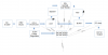
Looking at the diagram can you see any glaringly obvious mistakes?

Spec:

Input 0 -100V AC, 500mA fixed. Most of the time Vin < 25V AC.

Active rectification, 95% sync buck - absolute max efficiency < 36v

Terrible efficiency > 36v AC (can live with it).

FET prevents reverse voltage through active rectification (4 FETS) which means the PIC is doing the voltage comparison, not an expensive LT chipset.

Buck, Fets, Boost will be spec'd to withstand the 36V

Buck min voltage is 5.25v to give 4.75v (min USB spec)

Output: 5V, 3A max.

Operation:

Prevent DC backflow -> If (11) < (5) or 11 < 5.25v, turn fet1 off

Charge caps -> if fet1 on, turn boost on, turn fet2 off

Voltage dip -> if fet1 off, turn boost off, turn fet2 on

Voltage trip -> if (5) < 5.25 or (8) < 4.75v turn buck off, activate delay.

Notes:

The super caps have a useful range of 33v-5.25v. They will get hammered but will last longer than li-ion. I've found supercaps to have poor performance in the past, especially the Chinese stuff and wonder if the ESR will be too high in series to offer a meaningful current output. I'm looking for a 2 minutes at 500mA output when fet1 is turned off.

The PIC inputs (7) is for calculating Wout and reporting this and other stats via USART (9).

Frequency monitoring via TIMER0 may be added to the AC line or can be done using (11) in software. I don't know yet if a pin can be a trigger and ADC?
 

Attachments

  • theory_prototype.png
    theory_prototype.png
    72.6 KB · Views: 146
Instead of a Shunt on the front end, why not detect the voltage and "gate" it or allow it to pass if it's below a certain level? The active regulation needs to happen first though.

In the attached schematic, both PNP transistors need to be rated for more than 100V ... 250V is a good rule of thumb in this case. Only the output stage transistor needs to also be rated for the proper current.
 

Attachments

  • Z-REG.JPG
    Z-REG.JPG
    59.8 KB · Views: 125
Hi Beau, the PNP inflicts voltage drop which reduces efficiency at the lower end. This is very important, nominal AC in is circa 6V, 8.46v DC, with 5.25V DC being the buck cut off. Adding a further 1.2V drop as per the darlington arrangement inflicts a lot of efficiency damage.

Then there is the active regulation issue - fets which withstand 100V are either large or can't pass the current. They have higher resistances to deal with the voltage and the Vgs tends to be higher. Space is at a premium, I'm aiming to keep devices in SOT-23 packages.
 
Do you need isolation from the "power line"? What frequency 50/60hz or 400hz?

Anything from 10Hz to 300Hz. Sorry, I don't understand what you mean by isolation from the power line? If you mean the FET, yes if active rectification is used otherwise the power will flow backwards. An alternative is to use semi-activation (two fets, two sckhottkys) resulting in a 0.4v penalty.
 
Where are you getting this power? (very strange requirements)
10hz?? This will require a very large capacitor (at input). 300hz is not common. 400hz comes from airplanes.

Isolation: Not connected to.
Often there is a transformer in this type of power supply. It totally separates you from the power line.
I'm looking for a 2 minutes at 500mA output when fet1 is turned off.
Output: 5V, 3A max.
So when the 0-100VAC is present you want to output 5V at 3A.
But when power fails you want to last 2 minutes outputting 5V at 0.5A.
Does the load really drop from 3A to 0.5A when the power fails?

Input 0 -100V AC, 500mA fixed. Most of the time Vin < 25V AC.
What is "normal" voltage?
What is the minimum voltage it needs to work at? (you can not get power from "0V")
5V at 3A is 15 watts. So if the input is 5V it probably will take 4A from the AC voltage source.
At 10V it will draw 2A from the power source. assuming 15 watts
20V at 1A,
40V at 500mA
At 100V AC it will take 200mA.
" 500mA fixed" I don't understand. I think 500mA maximum, so the supply should shutdown below 40vac. Or maybe the load is really 3 watts 5V at 500mA)

How fast to charge the super cap? 2 minutes? This will require 2.5 watts (3 watts) from the AC source.
 
Last edited:
Adding a further 1.2V drop as per the darlington arrangement
That is not a darlington arrangement in post #3. Unfortunately, it also is not a 36 V regulator. At 37 V -ish, Q1 turns off Q2. No feedback = no regulation.

ak
 
That is not a darlington arrangement in post #3
...Correct

Unfortunately, it also is not a 36 V regulator. At 37 V -ish, Q1 turns off Q2. No feedback = no regulation.
... Sort of Correct again. It is a 36V Chopping regulator, where any INPUT voltage below 36V or the Zener voltage allows the output PNP to conduct. The voltage drop is only a couple hundred milliamps, not 0.6V and certainly not 1.2V


For the output transistor I was thinking more along the lines of a MJE5852GOS-ND as this is one I have used in the past in the circuit above with pleasing results.

PS. if you are worried about overall efficiency, then for sure I would find an alternative to a 36V shunt, and lose the linear regulator and instead use a switch mode regulator.
 
...Correct
... Sort of Correct again. .
I was responding to the TS, who called the transistor arrangement a Darlington and seemed to think the circuit was a linear voltage regulator.

There is no standard term or circuit for "chopping regulator". To me, it looks like an over-voltage protection circuit; the output is either essentially equal to the input and unregulated, or off. Since the input voltage is not stiffly regulated and there is no hysteresis or other feedback, the circuit probably will oscillate when the input voltage hovers near the zener value + 0.6 V

ak
 
the circuit probably will oscillate when the input voltage hovers near the zener value + 0.6 V
... Ahhh, I assumed that the input was AC from the mains, and in that case it wouldn't exactly hover. but your right as well, the circuit is more of a protection circuit ensuring that the output PNP only conducts when the input voltage is at or below the desired zener voltage.
 
Zetex ZXMP10A18GTA, 100 V, 3 A, 0.150 ohm Rdson, P-channel. Note that the device power dissipation and your desire for all SOT packages are at odds.

https://www.digikey.com/products/en...1&stock=1&quantity=0&ptm=0&fid=0&pageSize=500

You state the input can supply 0.5 A and the output current is 3 A. That is a 6:1 increase in current, which requires a 6:1 decrease in voltage for a theoretically perfect buck regulator. So you get 5 V / 3 A out of the buck regulator only when its input is above 30 Vdc. At 80% efficiency, that increases to 37.5 Vdc.

ak
 
We do not know enough to be designing any circuits yet. Too many unanswered questions.
 
>>It's a dynamo, power and frequency varies all over the place. I'm not expecting to switch the buck on at 10Hz, but there'll be enough power to run the PIC (I should have made that clear).
>>Dynamo, no transformer.

Where are you getting this power? (very strange requirements)
10hz?? This will require a very large capacitor (at input). 300hz is not common. 400hz comes from airplanes.

Isolation: Not connected to.
Often there is a transformer in this type of power supply. It totally separates you from the power line.


So when the 0-100VAC is present you want to output 5V at 3A.
But when power fails you want to last 2 minutes outputting 5V at 0.5A.
Does the load really drop from 3A to 0.5A when the power fails?

>> Normally it won't be 3A, USB varies, lets say 1A. It'll have to drop to 0.5A as I imagine super capacitors won't cut 1A or more. I'll experiment with this later!

What is "normal" voltage?
What is the minimum voltage it needs to work at? (you can not get power from "0V")

>> normal voltage is 6V AC, that's the normal voltage under load (a dynamo is fixed current, varying voltage) for a normal dynamo user.

5V at 3A is 15 watts. So if the input is 5V it probably will take 4A from the AC voltage source.
At 10V it will draw 400mA from the power source.
At 100V AC it will take 200mA.
" 500mA fixed" I don't understand. I think 500mA maximum, so the supply should shutdown below 10vac.

How fast to charge the super cap? 2 minutes? This will require 2.5 watts (3 watts) from the AC source.
Zetex ZXMP10A18GTA, 100 V, 3 A, 0.150 ohm Rdson, P-channel. Note that the device power dissipation and your desire for all SOT packages are at odds.

https://www.digikey.com/products/en/discrete-semiconductor-products/transistors-fets-mosfets-single/278?k=zetex&k=&pkeyword=zetex&pv612=639&FV=9780002,97c007c,97c0023,97c0029,97c002b,1f140000,ffe00116,980059c,98005c2,9800696,98007df,9800e00&mnonly=0&newproducts=0&ColumnSort=0&page=1&stock=1&quantity=0&ptm=0&fid=0&pageSize=500

You state the input can supply 0.5 A and the output current is 3 A. That is a 6:1 increase in current, which requires a 6:1 decrease in voltage for a theoretically perfect buck regulator. So you get 5 V / 3 A out of the buck regulator only when its input is above 30 Vdc. At 80% efficiency, that increases to 37.5 Vdc.

ak

True enough, the FET's would only need to be 0.5A rated, plus a small margin. The capacitor drain fet would be the exception.

You are correct on the calculations. The buck I'm intending to use is 90-95% which brings it into the 30-35v range I'm intending to regulate the voltage to.
 
...Correct


... Sort of Correct again. It is a 36V Chopping regulator, where any INPUT voltage below 36V or the Zener voltage allows the output PNP to conduct. The voltage drop is only a couple hundred milliamps, not 0.6V and certainly not 1.2V


For the output transistor I was thinking more along the lines of a MJE5852GOS-ND as this is one I have used in the past in the circuit above with pleasing results.

PS. if you are worried about overall efficiency, then for sure I would find an alternative to a 36V shunt, and lose the linear regulator and instead use a switch mode regulator.

During normal usage the higher voltages won't be reached, this can be thought of as an occasional spike lasting perhaps a minute or two at most.

The linear reg is only for the PIC where consumption is minimal.

Shunting the voltage > 33V is the trade off that allows for efficient FET's and no series transistor < 33V. It is more important to have maximum efficiency at the lowest voltage then efficiency when voltage is plentiful.
 
Last edited:
>>It's a dynamo,
30 or 40 posts in at least two threads, and you finally mention that. For someone focused on efficiency, that isn't.
the FET's would only need to be 0.5A rated, plus a small margin.
of at least 100%. The standard starting point for reliable component specifications is to double everything - capacitor voltage rating of at least twice its peak operating voltage, FET current rating of at least twice its peak operating current, etc.
The buck I'm intending to use is 90-95% which brings it into the 30-35v range I'm intending to regulate the voltage to.
Not my point. At 6 V or 8 V input and the output current you state, the buck will not operate.

ak
 
Great, moving on, I'm after application issues. I'm yet to spec out the components.

I've expecting 5V 500mA at lower voltage levels, rising as input voltage increases.
 
I know this does not meat specification but:
dynamo, 4 diodes, large cap=C9 which should be very large for 10hz but I found that 4700uF does work. (small in the picture for testing)
IC= LT8631 Vin<100 volts. I out=1.5A max.
The "PG" pin (Power Good) "PG2" tells the rest of the board that the output is good. +5V.
upload_2017-6-13_6-20-52.png

Here is the boost supply. It takes +5V and charges the super cap to 28.8 volts.
Note: The first boost supplies I tried pulled too much from the +5V and killed the supply. This IC is set to input current limit at 300mA to solve this problam. It only works when the first IC indicates the power is good. The boost shuts down when the input AC power stops.
upload_2017-6-13_6-26-3.png

The last IC bucks 30V down to +5V at 1Amax. Q1 turns it on/off from "PG2"
Note the two +5V buck supplies are connected together with out "switches" or diodes. PG decides which one will be on & off.

I know this will not work for you but I thought I would try something and see what happens.

Points to watch for:
* The boost supply must be input current limited so it will not eat up all the power.
* Two buck supplies can drive the same load.
* At 10hz (normally there must be a very large cap. But; it is OK for the buck to work only during the peaks of the AC and them the super cap will power the load during the valley of the AC.
* For the purpose of testing; reduce the value of the super cap and input cap so you don't have to wait for hours for spice to work. (a smaller super cap will charge faster for testing)
* Did not use any "active diodes" because they are very hard to make.
* Input buck supply set to stop working below 6V (about) to reduce load on the AC input. This gives the dynamo a chance to get up and running.
* There is no input current limiting. (500mA) That can be added. (not easy)
* The input 4 diodes could be high voltage Schottky diodes. (200 volts)
* Diode D7 is important. SPICE does not show this! Stops L3 saturation during startup.

Hope there are some ideas you can use.
Ron Simpson
 
Hi Ron,

The issue here is during normal use the buck and boost before the buck induce a minimum 25% efficiency penalty (based on the datasheet for those two IC's) across the voltage spectrum.
 
During normal use, only the first buck is working. (after the super cap is charged)
How do you get 25%? The idea to place the boost after the first buck came from your post #1.
I looked at a boost-buck to charge the super cap. (connects right after the 4 diodes) Did not find one that works at 150 volts, or 100 volts.

You are right that bucking down to 5V, busting to 30V and bucking to 5V is not good. This only happens when power is lost and you are running off the super cap.

You are right that the first buck is not real efficient. It is hard to find a high voltage efficient buck.
upload_2017-6-13_8-52-37.png
 
Status
Not open for further replies.

Latest threads

New Articles From Microcontroller Tips

Back
Top