Continue to Site

Welcome to our site!

Electro Tech is an online community (with over 170,000 members) who enjoy talking about and building electronic circuits, projects and gadgets. To participate you need to register. Registration is free. Click here to register now.

  • Welcome to our site! Electro Tech is an online community (with over 170,000 members) who enjoy talking about and building electronic circuits, projects and gadgets. To participate you need to register. Registration is free. Click here to register now.

A circuit equivalent of a DPDT switch?

Status
Not open for further replies.

Buk

Active Member
A simple circuit to implement the equivalent of a dpdt switch?
1635370866335.png


Has to be electronic as it has to operate at ~100kHz.

FWIW: This is the sort of thing I was after: https://tinyurl.com/ydvf78ma
 
Last edited:
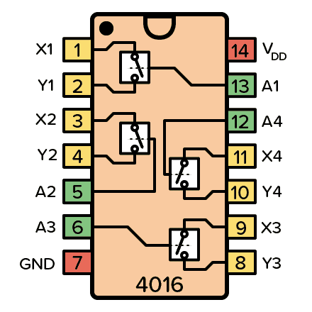
For analog applications -


What is power, voltage, current you are trying to switch ?


Regards, Dana.
 
What is power, voltage, current you are trying to switch ?
Something like these?
Thanks guys, but I'm really looking for a discrete circuit rather than an IC solution.

I'm driving a piezo chip which requires ~125V @ ~145kHz from a Li-ion cell voltage. I'm going to wind a toroidal transformer to do the lifting, but need to switch the DC to AC to drive the transformer. (I don't need PWM; this thing will either be on or off.)

My basic idea is to wind a tapped primary and switch the battery between the two halves of the primary coil so as to double the voltage range in the secondary.

Each half of the switch will need to control upto 4.2V @ ~10A. The 'switches' themselves will be used to drive mosfets to handle the current.

I hope to reduce the secondary current needs by tuning the secondary coil inductance to cancel some or all of the piezo's capacitance at the antiresonant frequency.
 
why not just use an inverter circuit? it does the same thing...
i've used this circuit in the past to drive non-rectifying flyback transformers:
hv-inverter.jpg


removing the diode on the secondary gives you an AC output.
 
why not just use an inverter circuit? it does the same thing...
Probably because I'm a Mech.Eng. swimming in water over my head :)

(I understand DPDT switches.)

i've used this circuit in the past to drive non-rectifying flyback transformers:
hv-inverter.jpg


removing the diode on the secondary gives you an AC output.

That looks much simpler than I've been playing with: https://tinyurl.com/yfxpqc4o

I am puzzled though. What sets/regulates the frequency?
 
Thanks guys, but I'm really looking for a discrete circuit rather than an IC solution.

I'm driving a piezo chip which requires ~125V @ ~145kHz from a Li-ion cell voltage. I'm going to wind a toroidal transformer to do the lifting, but need to switch the DC to AC to drive the transformer. (I don't need PWM; this thing will either be on or off.)

My basic idea is to wind a tapped primary and switch the battery between the two halves of the primary coil so as to double the voltage range in the secondary.

Each half of the switch will need to control upto 4.2V @ ~10A. The 'switches' themselves will be used to drive mosfets to handle the current.

I hope to reduce the secondary current needs by tuning the secondary coil inductance to cancel some or all of the piezo's capacitance at the antiresonant frequency.
WOW. That is a staggering amount of information to leave out of your original question.
Each half of the switch will need to control upto 4.2V @ ~10A.
That part deserved an encore.

ak
 
WOW. That is a staggering amount of information to leave out of your original question.

That part deserved an encore.

ak

I didn't so much leave out information, as confine my question to that which I wanted answered. Which I am still looking for.

I asked for a 'circuit' not an IC; equivalent to a DPDT switch. And I still want that.

unclejed613's suggestion my be a better solution to the underlying problem, but I wasn't looking for a solution to that problem. I wanted to try my idea for a solution.

Thereafter -- regardless of whether it worked or not -- I might have asked if there was a better solution. In this way, I learn.
 
Last edited:
MOSFETs would work and can switch fast enough. To make the equivalent of a DPDT switch you'd need at least 4 MOSFETs, and possibly 8.

You'll also need a driver circuit. You've got to switch two branches on after the other two branches turn off. When switching power, it is important that you never allow both branches to be on at the same time.
 
MOSFETs would work and can switch fast enough. To make the equivalent of a DPDT switch you'd need at least 4 MOSFETs, and possibly 8.
You'll also need a driver circuit. You've got to switch two branches on after the other two branches turn off.
That's pretty much where I've arrived at (since asking the question): https://tinyurl.com/ydvf78ma

It seems to work well enough for purely resistive loads.

Having trouble trying to make it work with my tapped transformer; but my understanding of inductive loads is sketchy to say the least.

This works after a fashion: https://tinyurl.com/yj4e2kkr
but the transformer ratio is screwed up in a way I do not understand.

When switching power, it is important that you never allow both branches to be on at the same time.

That's where I'll need (someone else's) experience rather than experimentation. I know mosfets can switch pretty quickly and cleanly, but I have no feel for whether there is any overlap?
 
Would it be simpler to use a h-bridge designed to drive inductive loads (motors) both ways without the need for a center tap.

Mike.
 
Would it be simpler to use a h-bridge designed to drive inductive loads (motors) both ways without the need for a center tap.
Its not a motor. It's a transformer that steps up the voltage to drive a piezo, that is resonance coupled with the secondary inductance.

Piezo's are highly capacitive, so (to quote from here(pdf))
It’s increasingly difficult and expensive to obtain high voltage and still achieve a high-frequency and high-current PZT driver amplifier. Fortunately, there’s simple solution to enable a lower-voltage piezoelectric amplifier to boost to higher volt-ages. A series-resonant technique can boost the driving volt-age and become a high-voltage driver and generator. Voltage boosting can be accomplished by adding a series inductor (Fig. 3). The next three sections offer detailed explanations on how a series-resonance circuit can boost voltage for capacitive devices.

And further down:
Impedance Cancellation

Referring to Figures 3 and 5, the series inductor is acting as impedance cancellation device. At the resonance frequency, both the inductor and the PZT capacitor have the same im-pedance, but an opposite polarity. They are 180 degrees out of phase. These two impedances cancel each other out. Thus, the inductor is a device that cancels capacitor impedance.Impedance cancellation is modeled as a virtual short circuit at resonance frequency. As shown in Figure 5, there’s a short circuit between the inductance and capacitor. This is because the two impedances cancel each other. The net impedance is zero. Because the impedance is always zero, the voltage is also zero at any current. By definition, it’s a short circuit.

And ultimately, the goal is:
For example, consider the setup in Figure 7 with 1-μF piezo-electric actuator capacitance and a 0.25-mH resonant induc-tor, plus a 100-V dc supply. At 10-kHz resonant frequency, the voltage across the PZT is 200 V p-p with ±6.5-A peak current. This is equivalent to 1300-W power. It’s achieved with just a 6.5-A and 6.5-V driver (42 W).
My needs are higher frequency and lower voltage )145kHz and 125V; but using a simple flyback circuit from a Li-ion battery; not the huge and expensive laboratory piezo driver units in the article.
 
The transformer winding connected to the piezo, plus the piezo capacitance, need to form a tuned circuit at the piezo resonant frequency.
Then play with the drive impedance - taps on the same winding, or a coupling winding - to get the most output for a given drive power.

Circuits for ultrasonic levitation should be a good start to show the basic principles, though you will need to adjust the operating frequency - one example here:
 
The transformer winding connected to the piezo, plus the piezo capacitance, need to form a tuned circuit at the piezo resonant frequency.
Then play with the drive impedance - taps on the same winding, or a coupling winding - to get the most output for a given drive power.
Thanks. I'm getting closer There is still a weird asymmetry between the two halves of the primary I do not understand.)

Now I'm looking for an oscillator chip that can do kHz and be tuned quite finely?
 

Buk,​

When I first saw "A circuit equivalent of a DPDT switch?" There was no schematic, no hint of how fast, does current flow one direction or two?, etc....
I suggested using a relay but then arrested the comment because there was too little information to comment. You knew about the transformer but I did not. On the other post every one complained about lack of information. Which you slowly added. Most posts, the first 20 comments are not right because we are just guessing on what the real question is.

Two Examples:
1) Wife, "Are you hungry", Me, "yes", Wife. "here is a cookie". Me, "thanks"
1) Wife, "Are you hungry", Me, "No", Wife, "you don't love me any more!", ....... 15 minutes of unhappy wife not saying what is wrong ..... What I should have said was "Yes, Dear lets go to a nice restraint. "

"Are you hungry" = I have food or I have no food, We are eating at home or eat out, I am making a plan about food or I have no plan, I am making food or you are making food, You are making me food or I am making food, I need help or I have finished with out you, was breakfast a good meal? which you did not say thank you for or hello ..........

I am trying to be funny, defiantly not angry. English is hard for me.
Communication is hard for me, ask my wife!
 
Now I'm looking for an oscillator chip that can do kHz and be tuned quite finely?
Look at an IR2153, a combined oscillator and push-pull FET driver:

It looks like something around 1nF and somewhere from 3 - 5K should give the 145KHz?

Just use a fixed resistor plus a preset to give a tuning range, rather than a fixed resistor only.
Or even add two presets, one 1/10th the value of the other, for coarse and fine tune.
 
Wife, "Are you hungry", Me, "No", Wife, "you don't love me any more!", ....... 15 minutes of unhappy wife not saying what is wrong ..... What I should have said was "Yes, Dear lets go to a nice restraint. "
I learned to answer only YES, please and thanks! It works
 
  • Like
Reactions: Buk
no hint of how fast,

This was in the OP right from when I first posted:
Has to be electronic as it has to operate at ~100kHz

With this: "the equivalent of a dpdt switch"
does current flow one direction or two?, etc..
*I* would assume both directions.

You knew about the transformer but I did not.

I do not see what relevance the presence of a transformer has to the question I asked. Nor for that matter, why the voltage/current/power are relevant either.

I was not seeking a complete solution to my overall design, just a hint as to how to implement this type of DPDT switching circuit; or a name for such a circuit so that I could look it up.

Once I found this:
1635429122548.png


I had enough information to allow me to rework the basic design to handle the load configuration requirements of the design, but finding that was difficult when I didn't know the term "H-bridge" was applicable. Searching for "electronic DPDT switching circuit" and dozen variations got me no where, which is why I asked. A search for H-bridge locates many examples and many variations; one of which was sufficiently close to lead me to the circuit I now have.

When I post a detailed description of this problem -- as I have before -- then I get inundated with a whole other raft of proposed solutions: "throw away the transformer and use a boost converter circuit"; "throw away the piezo and use a laser into a glass tube"; all of which are not applicable to my application and not where I want to go.

I hoped that by confining myself to the specific part of the problem I was having trouble with, I could avoid all the meta discussion. I failed miserably.
 
I do not see what relevance the presence of a transformer has to the question I asked.
Clearly, but that does not mean that they are not relevant, only that you don't know why. Can you see the difference?
Nor for that matter, why the voltage/current/power are relevant either
Because a 2N7001 cannot handle 10 amps. And, we still do not know about the power source(s) for the circuit, which might rule out using MOSFETs.
I hoped that by confining myself to the specific part of the problem I was having trouble with, I could avoid all the meta discussion. I failed miserably.
That is because your confining was based on your understanding of the overall circuit. If that understanding were correct, you wouldn't be having a problem.

---

CHAP. XVII. The Master said, 'Yu, shall I teach you what knowledge is? When you know a thing, to hold that you know it; and when you do not know a thing, to allow that you do not know it;-- this is knowledge.

Confucius (September 28, 551 – 479 BC)

OR, in American --

Know what you know, and know that you don't know what you don't know.

ak
 
Overlap in H Bridge or 1/2 H bridge "normally" handeld by dead time setting in
a PWM -

1635430992701.png


As you can see the PWM generates two non overlapping clocks for H Bridge, and dead time settable
in PWM, ph1 and ph2

Regards, Osc, its 145 Khz ....what resolution do you need ? How do you want to set it, with a pot or a V ?


Regards, Dana.
 
Status
Not open for further replies.

Latest threads

New Articles From Microcontroller Tips

Back
Top