be80be
Well-Known Member
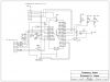
Not wanting to have to unplug my pickit2 to use it to test with I tried out this
circuit after a long look at the pickit2 and junebug to see what I didn't need.
This is what I came up with it works real good for 3 channel logic tool uses the pickit2 software. And from what I have tried the UART works to. Here some pictures of it. And the circuit too.
**broken link removed**
And a shot of the logic tool working
**broken link removed**
Attachments
Last edited:

