Continue to Site

Welcome to our site!

Electro Tech is an online community (with over 170,000 members) who enjoy talking about and building electronic circuits, projects and gadgets. To participate you need to register. Registration is free. Click here to register now.

  • Welcome to our site! Electro Tech is an online community (with over 170,000 members) who enjoy talking about and building electronic circuits, projects and gadgets. To participate you need to register. Registration is free. Click here to register now.

8A Current Limitter

Status
Not open for further replies.

davidbear

New Member
Dear all,

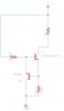
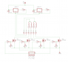
I want a circuit that will limit the current to my 24V motor controller to no more than 8A. Clearly this would be beyond the normal lm317 circuit, but I am wondering if a power transistor could be added to such a circuit to get the sort of performance I'm looking for?

Thanks for your kind replies,

DavidBear
 
Is this just to protect it against burning out when it's stalled?

Just add a PTC resistor (polyswitch/fuse) which will limit the current by tripping an automatically resetting when the load is removed.
 
Hero,

No, this is so that the traces on the PCB controller circuit wont get overly warm. Any other thoughts?

David
 
Thicker traces? You could always jumper the traces with real wire too
 
Hero,

No, this is so that the traces on the PCB controller circuit wont get overly warm. Any other thoughts?

David
Have you run solder along them?

They need to be thicker.

If you reduce the current, the torque and speed will also be reduced.

A polyfuse is still a good idea but only to protect it from meltdown, not for normal operation.
 
I forgot about running solder along the traces, although that only works if there's no mask on the board. I've seen a few car audio amps that thickened up their traces with solder.
 
Sceadwian,

Using 1 oz copper clad board and 8 Amps and accepting a 20 C rise in temperature, the traces are 0.137 inches wide; using 2 oz copper cuts that in half. I am not inclined towards widening the traces much more than that. I came across a circuit that looked like the attached file, but I was thinking that a 0.08 ohm resistor might be a bit inconvenient and a little questionable give that the Vbe of the BC547 might not be exactly 0.65V. So, I thought that it might be possible to put some sort of voltage regulator in its place and force the FJAF4310 to do the work. If this is a ridiculous thought, let me know how to use a PCT thermistor in this spot so that the current does not exceed 8A.

DavidBear
 

Attachments

  • limitter.png
    limitter.png
    3.6 KB · Views: 206
Hero's sollution to keep the traces from heating up is the easiest to implement, you simple apple solder along the entire length of the trace, effectivly doubling or better it's current handling ability. If you have protectant over the traces already you can simply run heavier gauge wire between the trace connections to bypass the current into the wire. PCB traces for heavy current are usually a bad idea because they take up so much space. Jumpers are very commonly used, and so is thickening them up with solder.
 
A 20°C temperature rise isn't much to worry about, unless voltage drop is creating a problem.

Either ways, run solder along the traces as I suggested earlier.
 
Last edited:
If you limit your current to 8A and the motor is stalled, the transistor will get incredibly hot.

Maybe you could reconsider your system architecture to keep the motor current off the board.
 
Yes, the transistor will get incredibly hot, but better that than burn out the motor. Can you think of any reason that I could not run a number of LM317 current-limiters (resistor between out and adj, Vo from adj) in parallel to deliver a total of 8A?
 
Yes, the transistor will get incredibly hot, but better that than burn out the motor.
Not if you use fold back current limiting.

Can you think of any reason that I could not run a number of LM317 current-limiters (resistor between out and adj, Vo from adj) in parallel to deliver a total of 8A?
A single LM317 will drop at least 3.75V even when it isn't limiting the current. Adding a booster transistor will increase the volt drop even more, possibly by as much as another 2V making a total loss of 5.75V.

Another potential problem is that the motor might not start when fully loaded because the current limiting is instantaneous and motors need a lot of current to start.

Use a Polyswitch as I keep telling you, here's an example:
**broken link removed**

RUEF800 8.0A POLYSWITCH FUSE (RC) 26-0825

A Polyswitch will also allow surges, it'll act like a slow blow fuse.

Going for a slightly higher rating fuse might also be a good idea.
 
Last edited:
Hero,

Again, thanks for the reply. I hope that I am not wearing your patience too thin.

Not if you use fold back current limiting.

I suspect that this is the root of my problem. What is fold back current limiting? And can you point me towards a web site that will help me understand it better? The polyfuses look great for stalls, etc., but I want to limit my current during normal operations. I will buy polyfuses and employ them. I realize that there are chips that will let me use Rsense to detect too much current and chop the signal off, but frankly that is beyond my comfort zone. I have been running my stepper with underpowered power supplies, so I have not had to worry about burning out my stepper. Recently, I have purchased power supply that will deliver more current than my stepper can handle, so I want to put a leash on it.

As far as using the LM317 as a current limiter, I find that I only loose a volt or two and get reliable current limiting in the circuits I've tried to build so far. I'm sure under the appropriate load you are correct, it just has not appeared that way to me yet.


WP100,

Thanks, I have clearly been looking at the wrong data sheet, I never saw design 906315 before. I think (but clearly do not know) that it is overkill for what I want. If you had a simplified current limiting circuit that could reach the currents that I am seeking, it would be a great boon. Otherwise I will continue to study the circuit you presented and see if I can more fully understand it.
 
Foldback limiting is when the regulator cuts the current to much less than the initial limit and only allows the full current to flow again when the current drops even more.

For example in this case suppose there's a short circuit causing the current to exceed 8A, instead of sitting there drawing 8A, the limiter cuts the current to 1A. When the resistance of the load is reduced to a point at which 1A can't flow (i.e. the load is removed) the limiter will reset allowing the full 8A to flow again.

There's nothing complicated about foldback limiting, a comparater with hysteresis is used to set the current levels.

You can also incoperate a low-pass filter so it will allow short surges.
 
I think we've assumed all along that it was a brushed DC motor, not a stepper. Altogether different discussion.
 
mneary,

Sorry if I seem to have changed the discussion. In my mind I have been talking about a (stepper) motor all along. In any event, I have enclosed a circuit diagram (that I originally noticed from PMinMO on a CNC site) that I am ultimately hoping to change to allow for a larger motor (it does not have the current limiter that I originally described, but a LM317T based one). Currently it is restricted to ~1.1 Amps (I think!). I will almost certainly take Hero's suggestion and incorporate a couple of polyfuses into this scheme.

Hero,

Where would the comparator with hysteresis go? I currently have no idea what you are talking about, maybe if I see it I will recognize it. Sorry for being so dense.

Thanks again
 

Attachments

  • unipolar2.png
    unipolar2.png
    13.3 KB · Views: 195
If your stepper doesn't have to achieve maximum speed or acceleration, then you can limit current by setting its Vdd to that voltage which causes the desired 8A to flow through the stepper's winding(s). All of the steppers that I've run in current-limited 24V (chopper) mode would work just fine without any current limiting circuit, at 5V or so.
 
Status
Not open for further replies.

Latest threads

New Articles From Microcontroller Tips

Back
Top