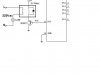
post your circuit ... but i'll try to describe how to connect it. First, you probably want to use NPN transistors and NOT the PNP you mentioned. For instance a TIP31 or 2N2222.
The collector of the transistor goes to +Vcc, the base through a 1k or so resistor to the output pin of your micro. The emitter goes to one of the coil pins on your relay. The other coil pin goes to ground. You also want to put one or two diodes in the circuit. I usually use two. One of them has the anode at the emitter of your transistor and the cathode at +Vcc. The other has the anode at ground and cathode at the emitter. This way any back emf from the relay wont blow your transistor and/or micro port. Not many micros like 500V at their outputs.