Continue to Site

Welcome to our site!

Electro Tech is an online community (with over 170,000 members) who enjoy talking about and building electronic circuits, projects and gadgets. To participate you need to register. Registration is free. Click here to register now.

  • Welcome to our site! Electro Tech is an online community (with over 170,000 members) who enjoy talking about and building electronic circuits, projects and gadgets. To participate you need to register. Registration is free. Click here to register now.

8 bit timer help

Status
Not open for further replies.

andy257

Member
Hi Guys

Struggling to see why my circuit isnt working as i had designed. Can someone advise as to what might be the problem.

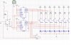
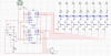
Basically i am using 2 x (74163 4 bit counters) a sig gen to produce a slow clock and a D type FF for a trigger.

Basically what i have designed it to do is count to the binary sequence 0010 1011 and then reset. The circuit is triggered by the push button, when the sequence is reached the count should stop and wait for another trigger.

Its actually reseting on the sequence 0000 0001 and i cant figure out why. It should work in my eyes, perhaps its something stupid i cant see.

The leds are just there for me to see a visual output.

Andy
 

Attachments

  • 8bit.jpg
    8bit.jpg
    179.3 KB · Views: 428
I'm assuming that 0000 0001 is LSB......MSB. When you decode a counter, even a synchronous one like this, you will get glitches from your decoder (AND gate). This is clocking your reset FF. Try the following:

1. Move your start switch to Reset on the FF.
2. Reset the counter from ~Q.
3. Connect the output of your decoder gate to the D input, instead of to clk.
4. Clock the FF.
This will make your reset synchronous, avoiding the glitch. You may still occasionally have problems on startup, because the removal of the reset is not synchronous.

You need to move the LEDs to the collector circuits, in series with the resistors, and add a 10k resistor in series with each transistor base. The way you have it, you will only get about 2.7V logic 1 levels, with no predictable base current limiting. Your guaranteed worst-case logic levels (for LSTTL, anyway) will still only be about 2.7V (they will typically be higher than this), but at least you have predictable base current limiting.
 
Ron H said:
I'm assuming that 0000 0001 is LSB......MSB. When you decode a counter, even a synchronous one like this, you will get glitches from your decoder (AND gate). This is clocking your reset FF. Try the following:

1. Move your start switch to Reset on the FF.
2. Reset the counter from ~Q.
3. Connect the output of your decoder gate to the D input, instead of to clk.
4. Clock the FF.
This will make your reset synchronous, avoiding the glitch. You may still occasionally have problems on startup, because the removal of the reset is not synchronous.

You need to move the LEDs to the collector circuits, in series with the resistors, and add a 10k resistor in series with each transistor base. The way you have it, you will only get about 2.7V logic 1 levels, with no predictable base current limiting. Your guaranteed worst-case logic levels (for LSTTL, anyway) will still only be about 2.7V (they will typically be higher than this), but at least you have predictable base current limiting.

Hi Ron thanks for the input. I tried what you said. I still seem to be getting the error.

Basically what it needs to do is:

press button
counter starts
counter reaches 180 (binary 0010 1011)
circuit stop

the circuit is configured how it should operate however like i posted above i am not able to rest at the correct value. Ive put a logic analyser on this and it shows all bits to be high except MSB which is, on that clock pulse, low going high

11111110 going to 00000001 - this is the error when my circuit stops

Any other suggestions?

Cheers

Andy
 
This is what I described. So is this what you now have?
BTW, what kind of D FF are you using?
 

Attachments

  • 8bit_rev.png
    8bit_rev.png
    310.3 KB · Views: 320
Status
Not open for further replies.

Latest threads

New Articles From Microcontroller Tips

Back
Top