Continue to Site

Welcome to our site!

Electro Tech is an online community (with over 170,000 members) who enjoy talking about and building electronic circuits, projects and gadgets. To participate you need to register. Registration is free. Click here to register now.

  • Welcome to our site! Electro Tech is an online community (with over 170,000 members) who enjoy talking about and building electronic circuits, projects and gadgets. To participate you need to register. Registration is free. Click here to register now.

74Ls47 and 74Ls90 error count

Status
Not open for further replies.

indrenz

New Member
Hello to all,

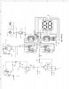
I've built this Led event counter using 74ls47 and 74ls90 from this site...

https://www.electronics-lab.com/projects/misc/012/index.html

it works fine by itself, ...but whenever I integrate this counter to another circuit using a DPDT relay controlling the On and off Function of an AC induction motor, the counter leds gives a false reading every time the control relay cycles to swicth On and Off.

I integrated the counter circuit to monitor how many times the induction motor (contolling a water pump for a reservoir) had run for a given day. But as I said everytime the pressure switch or the relay energizes...it gives a false reading or sometimes the counter resets to Zero. The counter works fine only if there are no relays to activate.

Please need help, Thanks,
inrei :) :)
 
Last edited:
That input needs to alternate between +5 V and ground, not open. If you don’t have a pull down resistor on the input, you need one.
Relays like most switches don’t make and break cleanly. The contacts bounce or slide so you may get 5 or more counts before it settles. Search for “debounce circuits” to clean up a “dirty” signal.
 
a DPDT relay controlling the On and off Function of an AC induction motor
I assume the relay is in parallel with the input to the counter and controlls the motor? Make sure there is a catch diode accross the DC coil of the relay. Also make sure there are some 0.1uF caps accross each 74LS90s power pins in your circuit. They don't show that on the page but it is essential for glitch free operation of TTL circuits.
As ClydeCrashKop mentioned, a debounce circuit will be required if you are triggering the counter circuit from a pair of mechanical contacts. A 74LS14 schmitt buffer, 4K7 resistor and 10uF cap make a simple debouncer.
 

Attachments

  • DEE-bounce.gif
    DEE-bounce.gif
    2.1 KB · Views: 370
Above suggestions should work fine.

The 100 nF caps are a must for TTL across the powerpins of the 7490 and 7447 IC's because the ic's themself cause dips on the 5 volt dc rail because of their internal switching logic.

Other option to bear in mind is to get an electromechanical impulse counter from a surplus shop or ebay for a couple of dollars which will give you the total number of events.
Some may have a reset option to put the numbers back to zero if required.

You can that way check the reliability of your TTL counter too over a period of time if it count's more impulses because of contact bounce.

and use the TTL for
 
Event Counter

RODALCO said:
Above suggestions should work fine.

The 100 nF caps are a must for TTL across the powerpins of the 7490 and 7447 IC's because the ic's themself cause dips on the 5 volt dc rail because of their internal switching logic.


Thank you all, for the help...

Here is the circuit diagram for the event counter, I've manage to connect a debouce circuit using a CD4013 one-shot and latch and I've seen a lot of improvement...athough there still some minor error, probably adding those 100 nF across the powerpins will do it perfectly.

Thanks to all...again:) :)
 

Attachments

  • event counter.JPG
    event counter.JPG
    274.1 KB · Views: 586
Status
Not open for further replies.

New Articles From Microcontroller Tips

Back
Top