futz
Active Member
Old quote 
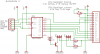
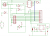
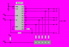
Just did. Needed a break from the balancer, so I built a Predko style **broken link removed**. Works good.blueroomelectronics said:Ever tryed Myke Predko two wire LCD circuit?