Continue to Site

Welcome to our site!

Electro Tech is an online community (with over 170,000 members) who enjoy talking about and building electronic circuits, projects and gadgets. To participate you need to register. Registration is free. Click here to register now.

  • Welcome to our site! Electro Tech is an online community (with over 170,000 members) who enjoy talking about and building electronic circuits, projects and gadgets. To participate you need to register. Registration is free. Click here to register now.

74HC14 output to 4066

Status
Not open for further replies.

prprog

Member
Hi

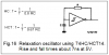
I breadboard this little circuit that make the led turn on/off at different intervals depending on the light over the Cds cell. How do I connect the output to a 4066 control pin? I want to activate the 4066 with the on/off cycle of the 74HC14. I try connecting at point A or point B, but it did not work. I also try it without the LED.

Thanks,
PRPROG
 

Attachments

  • Led_Cds_Osc.GIF
    Led_Cds_Osc.GIF
    4.9 KB · Views: 1,532
If you look at the datasheet, a 74HC14 has logic inverters with Schmitt Trigger inputs.
So connecting a photo-resistor between an input and an output with a capacitor to ground on the input makes it be an oscillator that turns the LED or the 4066 on and off over and over. The speed of the switching depends on the amount of light on the photo-resistor.
 

Attachments

  • 74HC14 oscillator.PNG
    74HC14 oscillator.PNG
    9.1 KB · Views: 3,173
Thanks Audioguru, that explain why the LED turn on/off at intervals. But when I try to connect the output to the 4066 it does not activate the 4066 switching. Can you please tell me how do I connect the oscillator ouput to the 4066 ? In the diagram I identify the 2 points where I try connecting the 4066 control pin. None of those 2 work. I think that the 74HC14 ouput does not have enough voltage (?) for the 4066 to turn on?????
 
The 74HC14 and the 4066 must both use THE SAME supply voltage and ground.
Point A on your schematic is the output of the 74HC14 that swings almost from the supply voltage to almost ground which is plenty to turn on and off the 4066.
If the light is very bright (sunlight or a laser beam) then the resistance of the photo-resistor is too low for the output of the 74HC14 to drive and the voltage swing will be low or the oscillator will stop.
Add a 1k resistor in series with the photo-resistor to prevent it.

Both IC's used the same power voltage and group. OK.

Let see if I get your suggestion correctly; I will add a 1K resistor from the photo-resistor to the output. Correct?

This change, will allow the ouput of the 74HC14 to drive the 4066?

Thanks,
PRPROG
 
Both IC's used the same power voltage and group. OK.

Let see if I get your suggestion correctly; I will add a 1K resistor from the photo-resistor to the output. Correct?

This change, will allow the ouput of the 74HC14 to drive the 4066?
Yes, when the light is very bright.
 
Thanks Audioguru it works as expected. Why adding the resistor from the Photo-resitor to the output make it work?
The output level from the 74HC14 reduces when it drives a low resistance load. When the output level is less than the input threshold levels then the oscillation stops.
The resistance of the photo-resistor is low when the light on it is bright.
Adding the resistor in series with it increases the minimum resistance so the 74HC14 can drive it.
 
Status
Not open for further replies.

Latest threads

New Articles From Microcontroller Tips

Back
Top