Electro Tech is an online community (with over 170,000 members) who enjoy talking about and building electronic circuits, projects and gadgets. To participate you need to register. Registration is free. Click here to register now.
Welcome to our site! Electro Tech is an online community (with over 170,000 members) who enjoy talking about and building electronic circuits, projects and gadgets. To participate you need to register. Registration is free. Click here to register now.
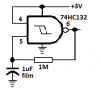
50 74HC132 SOP-14 werd tested as freerunning oscillator. Two thirds failed: one or more gates of 4 per IC failed to act as oscillator (1M and 1uF). They were obtained from 2 or 3 sources, unfortunately I can't distinguish from which.
What is the forum's comment on this?
Did you try NOT loading the output of the oscillator outout with the LED and resistor but buffering the output using one of the other gates to drive the LED ?
Did you try NOT loading the output of the oscillator outout with the LED and resistor but buffering the output using one of the other gates to drive the LED ?
Did you try NOT loading the output of the oscillator outout with the LED and resistor but buffering the output using one of the other gates to drive the LED ?
With a supply of 6V a 74HC IC has an output current of 26mA when it is shorted. But it will not oscillate when its output is shorted and some will barely oscillate in your circuit when the output current is 8.7mA.
With a 4.5V supply then the output current is only 15mA when shorted and some barely oscillate when the load is 5mA.
With a supply of 2V or 3V then guess how little output current will prevent oscillation. The LED won't light up anyway.
This site uses cookies to help personalise content, tailor your experience and to keep you logged in if you register.
By continuing to use this site, you are consenting to our use of cookies.