Continue to Site

Welcome to our site!

Electro Tech is an online community (with over 170,000 members) who enjoy talking about and building electronic circuits, projects and gadgets. To participate you need to register. Registration is free. Click here to register now.

  • Welcome to our site! Electro Tech is an online community (with over 170,000 members) who enjoy talking about and building electronic circuits, projects and gadgets. To participate you need to register. Registration is free. Click here to register now.

72 Watt 87 Volt LED Driver, 12

Status
Not open for further replies.

kinarfi

Well-Known Member
According LTSpice,this should work, I can get close, but no matter what I try, I have been unable to get much past 80 volt and 700 ma which then drops off around 5 - 600 ma after around 15 seconds as thing settle in. I tried several inductors and the last one had 2 toroid core with 6 turns and didn't seem to any better than the small one, but the FET did get hot enough for the solder to melt and turn the circuit off.
Does any one have any suggestions?
 

Attachments

  • 20130214_144402.jpg
    20130214_144402.jpg
    1.6 MB · Views: 302
  • 20130214_144344.jpg
    20130214_144344.jpg
    1.7 MB · Views: 370
  • 72 Watt 87 Volt 02-2013-3 .asc
    5.2 KB · Views: 192
What parts are you using. D1 needs to be real fast!
You appear to be running at 300khz. That is quite fast.

You know there are real PWM ICs that do this job. A 555 is not built to drive a MOSFET gate at 300khz. I think the MOSFET is being turned on/off too slow because the 555 can not drive a large amount of capacitance. I think you have AC losses in the MOSFET that are too high.

Some of your parts do not work on my computer (pot and voltage regulator) so I shorted out the top two leads of the pot. I used 8 volts to run the 555. What voltage is the 555 running from?

Heat sink on MOSFET???? Your current is high. Work out the DC loss in the MOSFET with the 6A current when things are running. It is high. During start up the current is 18A too much for that part. Your DC loss alone will kill the FET with out a big heat sink.
 
here's the corrected schematic with parts that should work with any LTSpice, the actual FET and Diode numbers are in blue.
As I tried it with a different number of turns, 5 to 8, the scope trace of current looked the same and the voltage and current through the LEDs remained about the same, less than a 10% change from 5 to 8 turns. The heat sink was large with lots of fins and a fan and the copper piece on the top of the fet was for heat dissipation of the drain lead and it still melted and let go, but didn't ruin the fet, as best I can tell and only let go as I got down to 5 turns, at which point I quit and opened this thread.
FET is a IRFP460LC 500V .27 ohm 20 A taken from server power supply
Diode is a STTH10R04D 400V - 10A from Digikey
Thanks for you advice
Kinarfi
 

Attachments

  • 72 Watt 87 Volt 02-2013-3 .asc
    5 KB · Views: 183
Ron, is there any particular IC that you would suggest using?
 
Your diode is good.
You need a bigger FET.
With spice, when things are regulation you have 2V across the FET at 8A so the watts are BIG.
Frequency =375khz.
Try changing the 1.3 current sense resistor to much larger, maybe 13 ohms and get the thing running. Then work on getting more power.
In real life you need a capacitor across the input supply. 14 volts. It needs to be close to L2, M1.
You start up condition is very destructive. Now with out current limit the current goes very high. The FET has 8 volts across it at BIG current!

Look at TL284x. The TL2844 or TL2845 have a 50% duty cycle limit that is good for this application. This part is also known as USC3845 and many companies make it under slightly different names. The UC284x is a very old part. I first used it in PC power supplies for Samsung. It is most ofter used in off line supplies but it works very well for low voltage applications (14v). It likes to run in boost mode like you have.
 

Attachments

  • uc2845a.pdf
    3.8 MB · Views: 194
Thanks, I've been looking at the UC3845A, not the 3844, and also the TPS20411, but the are so darn small! I'll let you know where I go next.
I would thing that the IRFP460LC would be big enough
ID @ TC = 25°C Continuous Drain Current, V GS @ 10V 20
ID @ TC = 100°C Continuous Drain Current, V GS @ 10V 12 A
IDM Pulsed Drain Current 80
I do have a large cap between circuit and power supply, in the mFs, but it has about 12" of wire per lead. I'll fix that.
May have a UC3845 in stock.
Thanks again,
Kinarfi
 

Attachments

  • 20130215_093632.jpg
    20130215_093632.jpg
    115.4 KB · Views: 228
I may have been wrong. The parts that do not go beyond 50% might be wrong. I need to think on that. The UC384x come in 8 pin dip package if you can find one.
 
Yea, it's hard to make 90 volts out of 12 with a standard boost converter. By the time you take into account the voltage drop across the FET, inductor and diode a duty cycle of 90% or so is needed. Usually most designs don't go over 60%. I can get it to run at about 65Khz with 100Uh inductor. But the ripple current in the output cap it way to high. I think its aggravated by the LED current going to 0 slightly below the 87 volt point. You can get rid of the big start up current by adding a .1 ohm in the source of the FET then a little current sense transistor that resets the 555.
I can't even find a circuit in web bench.

Here is one. Pretty fancy.

https://www.linear.com/product/LTC3862-2
 
Last edited:
I agree with RonV. There is too much boost.
Consider using the two LEDs in parallel. The boost will be 40 volts at twice the current.

To parallel the LEDs you need two current resistors. You started with a 1.3 ohm resistor so use two 1.3 ohm resistors, one for each LED. The transistor Q1 will need two 100 ohm base resistors.

How did you get n=23 on the bottom LED and no n=1 on the top LED? I want to have n=17 on both.
 
If no n or m, one is assumed, I guess.
Here's what I did for my son, he has 2 lights with 12 3 watt LEDs each, one driver and 2 LM317 current regulators,which is what you suggested, I set the voltage high enough to allow for the overhead of a LM317, but just barely high enough for the LM317 to work and still keep the heat dissipation to a min. The LT1270A is the easy way out if you don't exceed it's limits, but not as challenging and fun as trying to get 87 volts :). By the way, I did get well over 150 volts when I unloaded it for a moment, had to kill the power in a hurry because it was making weird noise and exceeding the cap voltage.
 

Attachments

  • post.png
    post.png
    40.1 KB · Views: 215
  • Light Bar+2LM317-2.asc
    3.9 KB · Views: 137
The two diodes in you 555 project; one diode is (1) and the other diode is (23 diodes). I can not change the n=23. I wanted to make both diodes have n=17 but I can't see how to do that. When I right click I can not change the n value, or add a n value.
_________________________________
Edited
I see, Don't click on the diode, Click on the name. It works now.
 

Attachments

  • 72 Watt 43 Volt .asc
    5.2 KB · Views: 147
Last edited:
Here is a neat calculator. If you plug in your frequency and voltages it will kick out an inductor.

https://www.daycounter.com/Calculators/Switching-Converter-Calculator2.phtml

I picked a big inductor out of spice and changed frequency till I hit it.

I used 1.7 volts for the diode, 1.89 for the FET and .7 for the current sense resistor.

12.6v for the input and 87v @ 840ma for the output. I then set the nominal frequency and duty cycle for the 555 without the current limit or feedback from the LED current. Then adjusted LED current via POT and last set the current limit just above the required current.
 

Attachments

  • poor boost.asc
    5 KB · Views: 137
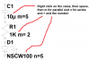
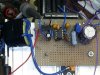
Unfortunately, one of my specs s to use what I have on hand, so this is what I ended up with
post.png
I did away with the input current controls, they kept if from running, and then after that, it didn't seen to matter what the inductor was, all I could get with a ~100 ohm load was `67 volts and ~700ma, I wanted 800 ma.
Then I changed the load to ~50 ohm and I got ~45 volts and ~1700ma and it didn't seem to matter which inductor I used, from 200uh to 8 uh, same voltage and same current plus or minus, but it's good enough for what I have to drive. But if I can't get the 87 V and 800 ma ande have have to settle for driving 2 sets of LEDs with on driver, I guess I'll see if I can drive 4 strings from one driver and use 4 LM317s, probably go with a LT1270A.
I ran 7 amps through the FET, Vsg<10, and had a Vsd of 1.6V and 6.9A through the diode gave me a drop of 1.06 V.
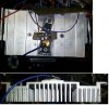
Because of the heat generation, I found the use of an old hair dryer with it's 3 winding of 50,30, and 20 ohms very handy, especially with it's cooling fan.
Kinarfi
PS Thanks for your help, apparently, I am trying for too much boost.
 
Last edited:
Status
Not open for further replies.

Latest threads

New Articles From Microcontroller Tips

Back
Top