Follow along with the video below to see how to install our site as a web app on your home screen.
Note: This feature may not be available in some browsers.
R said:Hello guys,
What to do for 7 segment decoder, actually i have done project with 7447 with small/ 1 chip red leds at 5v.
But now i have 5 leds in series with 120ohms.
How to decodes this voltage is at 12V .
So what's your problem? All the criteria seems to be met... If it works what is the issue..Hello,
The Vcc is 12.42 right now is adapter SMPS after that there will be transformer!
total current is 222mA for 0 in 4 digits!
the voltage across string is 9.96V, Vf of led is 1.92V, current per segment is 8.89mA and voltage across resistance is 1.8V.
I HAVE POSTED ALL INFO.You multimeter most likely has a series resistor like 10 or 100 ohms when measuring current. That's why we asked for th voltage across your resistor rto get current.
I HAVE POSTED ALL INFO.
The Vcc is 12.42 right now is adapter SMPS after that there will be transformer!
total current is 222mA for 0 in 4 digits!
the voltage across string is 9.96V, Vf of led is 1.92V, current per segment is 8.89mA and voltage across resistance is 1.8V.
Hello,
There is some problem as THE PLC work in 24V and this circuit at 12V.
The Input are connected to Gnd with pull down of 10K, when the inputis connected to 12V it work as BCD 8421 on display.
But when i use external 24V the Gnd of both are common and the 24 to input the signal does not work well.
how to connect both of PLC 24 nad internal 12V led display together
(24V PLC)
|
[10k]
|
(tap to 12V decoder)
|
[10k]
|
(common gnd)
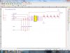
Why is there a transformer after the SMPS? IF the SMPS output is 12.42VDC, and the other numbers you report are all correct and prevail across all operating modes, then there is no need for a transformer, nor would one do anything for you, as DC won't go through a transformer.
i have no idea of CAN.You CAN communicate from the PLC
Hello,I am using 24V supply here in industry there will be 24V operated PLC.You can divide the 24V from the PLC to the 12V you need fro the decoder with a series pair of 10K resistors on each line.
Code:(24V PLC) | [10k] | (tap to 12V decoder) | [10k] | (common gnd)
Yes, I know...The logic supply has to stay within the logic supply range. If your feeding 24 V to the inputs of the 4511 expect smoke.
Hoorayyy!!!Yes, I know...
Here is schematic