Continue to Site

Welcome to our site!

Electro Tech is an online community (with over 170,000 members) who enjoy talking about and building electronic circuits, projects and gadgets. To participate you need to register. Registration is free. Click here to register now.

  • Welcome to our site! Electro Tech is an online community (with over 170,000 members) who enjoy talking about and building electronic circuits, projects and gadgets. To participate you need to register. Registration is free. Click here to register now.

7.2 V 3A Transistor Switching

Status
Not open for further replies.

tiwari.sachin

New Member
Hello

I have a device (a printer) which will work on 7.2V and requires about 2.5 amps. I need to design a circuit that will supply the voltage only when required. Hence i decided to use a transistor for the switching. I am not too sure which transistor to use. Can anybody kindly suggest me the option for the same. Or for that matter, will a simple switching circuit actually work for this configuration?

How about using TIP31.

Datasheet of TIP31 : https://www.electro-tech-online.com/custompdfs/2010/11/TIP31A.pdf

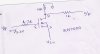
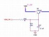
I have also attached the schematic that i am using now. Is it actually the right way to do for the required voltage and current.

Your advice will be very helpful.

Regards
Sachin
 

Attachments

  • transistor switching ckt.JPG
    transistor switching ckt.JPG
    11.7 KB · Views: 251
You have the transistor connected as an emitter-follower instead of as a switch. Its datasheet shows a max saturation voltage loss of 1.2V if its current is 3A and with a base current of 375mA.
With a current of 2.5A then its output is about 6.2V if it has a base current of 250mA.
For a base current of 250mA the 1k base resistor needs 250V across it and VDM ON will need to be about +257V.
 
My idea was to steer him to a P-channel MOSFET, but we need to know the control voltages.
 
His idea will have his 1k base resistor dissipating "only" 62.5W when its input is +257V.
 
Or you should just use a relay, the transistor will have a voltage drop from collecter to emitter
 
To make things clear. I need to provide 7.2V, about 3 Amps to a device (a printer head). This should not be continuous as the head will heat up. The controller will control this by use of a circuit that i have shown. The controller used is LPC1768 and this works on 3.3V Logic

Since the above discussions show that I am not doing it the right way. I am also thinking of having a P Channel MOSFET which will inturn be driven by a PNP Transistor. (This was also suggested in one of the forum, although i am not sure the exact parts that i could use)


Any suggestion on this gentlemen :)
 
Last edited:
BEN. I can use a relay, thats probably the simplest option but not the most economical and ofcourse quite a space consuming part on board
 
IRF9540 p channel mosfet will do the job, putting the gate to 0V will turn it on, putting the gate to VCC will turn it off, if you need reversed logic use a 2N7000 n chanel mosfet as an inverter
 
@Thunderchild Is this what you are suggesting. Let me also see if the component is available locally. Meanwhile a small schematic will be very helpful.
 

Attachments

  • sch 001.jpg
    sch 001.jpg
    152.9 KB · Views: 148
source of the IRF9540 does to VCC the drain to the load, a resistor goes from gate to source. The gate of the IRF9540 is connected to the drain of the 2N7000, the source of the 2N7000 goes to GND, the gate of the 2N7000 is connected to your drive circuitry. you may want a resistor from the gate of the 2N7000 to ground.

what country are you in ?
 
Last edited:
I am trying the schematic with the circuit description, you told me. I will post once i am done. Meanwhile what do you mean by collector for 2N7000. Its a MOSFET. I guess it is drain that you meant. Kindly clarify
 
Status
Not open for further replies.

Latest threads

New Articles From Microcontroller Tips

Back
Top