Continue to Site

Welcome to our site!

Electro Tech is an online community (with over 170,000 members) who enjoy talking about and building electronic circuits, projects and gadgets. To participate you need to register. Registration is free. Click here to register now.

  • Welcome to our site! Electro Tech is an online community (with over 170,000 members) who enjoy talking about and building electronic circuits, projects and gadgets. To participate you need to register. Registration is free. Click here to register now.

6v Regulator for a Generator System

Status
Not open for further replies.
The main switch (according to the manual): It has three positions, mainly for lighting. In all positions the ignition circuit is "on."
To the right, the low beam headlight is on.
At center position, the high beam headlight is on.
To the left, the parking lights are on.

Summary;
Resistance between generator Df and ground is 1.8 ohm
Between generator D+ and ground is 0.5 ohm
Between D+ and Df is 1.2 ohm

All of these reading take into account the 0.3 ohm between the test probes, i.e. I subtracted 0.3 from the measured readings.
 
Thanks. Those measurements are helpful, reasonable and about what one would expect.
I'll have to get my head round the Benelli diagram; it doesn't seem to tally with your description of the main switch operation. My reading of Benelli is that the switch on the right, just below the regulator, is the high/low beam switch? And no parking light is shown. Are you positive that the Benelli circuit (give or take its errors) is the same as you actually have on your particular bike? Does the manual include that exact circuit or some other?
 
I was reading off the description from the manual. The manual may not be accurate, as it's a translation from Italian.

I think it's correct to say that the ignition key (central 3 way switch) also controls the parking and headlight. That's normal for continental motorcycles of this era. Insert the key and it depresses a contact to enable ignition. Turn the key one way and the head light is on. Turn it the other way and it's only parking lights. Where the manual says it also controls the hi - lo beam may be an error.

Especially since you're right is seeing that a hi-lo beam switch does exist (the one below the regulator). Sharp eyes, Alec.
The "parking lights" may be nothing more than the taillight (yellow wire) and a torpedo bulb in the headlight shell. That's normal for cycles of this era.
 
From the Benelli circuit it looks like the ignition coil gets its supply only via a 6V3W indicator bulb. Surely that's not right?
 
The diagram is not clearly made, but try following the blue battery main wire. That goes to the bypass switch, then to the main terminal panel (3c) and the ignition switch. Then a green wire to the ignition coil. I'm not saying that's correct, or even the best way.

The ignition circuit is unique (and strange); normally the ign. coil is fed by the battery, but if the battery's dead, you throw the "emergency bypass battery switch" and that cuts out the battery. Coil is now fed by the generator to push start the bike. The set up is great for a stranded biker, but adds another layer of complication to the circuit.
 
Ah, if those two black lines (like a capacitor symbol) and an arrow represent the ignition switch it makes sense. I was reading that as the horn button. Presumably then the horn button is the sticky-out bit of the high/dip switch just below the regulator?
The battery bypass switch has a dotted-line circle (black wire from it). Am I right in thinking that represents a temporary contact which would be made when starting the engine (to supply battery voltage to the field winding before the dynamo gets up to speed)?
 
Yep, I think the side button (green wire) on the hi-lo light switch is the horn.

Your read on the dotted circle at the bypass switch makes sense; that it gives a temporary starting current from the battery to the field coils. Except I don't know how it disconnects after the engine starts. Could the disconnect happen at the mechanical regulator? I recall a such a disconnect relay in the regulator description.
 
Except I don't know how it disconnects after the engine starts.
I was thinking it might be like a car ignition switch operating the car starter motor (though in your case there's no such motor). The key/knob acts against a spring, so the switch is closed only briefly and opens again under spring pressure. Does the switch have a spring return action when turned in one direction?
Could the disconnect happen at the mechanical regulator? I recall a such a disconnect relay in the regulator description.
That particular disconnect is to prevent the battery draining when the dynamo isn't running.
Can you post a link to the manual (albeit in Italian) for your bike model?
 
The switch has two positions, with no return spring. So so it's either battery coil start, or generator coil start.

I am traveling right now, so I don't have a copy of my Sears/Benelli 350 manual. However a search pulled up a copy of the 250cc manual, which should have an identical wiring system. Better yet, this manual is a different version, with a better wire diagram.

Standby, I'm having some difficulty uploading the file.
 
The switch has two positions, with no return spring.
Then it's a mystery (to me!) why the black wire coming from the reg Df terminal goes to the bypass switch. What does it connect to? What is that dotted circle there for?

Edit: If you can't post the manual file here, perhaps you could put it on a shareable drive (Googledrive or whatever)?
 
Let me know if the link above doesn't work. Attached is another version of the wire diagram, but print quality is poor. I'm working on getting a better version.
 

Attachments

  • tmp_968-250-360_Wire Diagram 3rd version-1491447639.JPG
    1.8 MB · Views: 454
The dropbox link works fine. Interesting that the wire colours in the P15 circuit are different from those in the post #52 link!
 
The dropbox link works fine. Interesting that the wire colours in the P15 circuit are different from those in the post #52 link!

Now that I look at it, yes. Not only are some colors different, but the wiring is slightly different. To add to the mix, I found yet another version of the diagram (is this the 3rd or 4th?).

Looking at my bike's wires, the correct diagram is the one I attach now. Thank you for sticking through this.
 

Attachments

  • Wire Diagram.jpg
    Wire Diagram.jpg
    245.2 KB · Views: 527
Ok. I think we're good to go with that.
I've redrawn it more logically, to make it's function easier to follow:
6VBenelliWiring.PNG
Let me know if you spot any errors.
I've simulated a first effort at a regulator which should do what the mechanical one does, plus provide better control of the battery charging. Voltage is limited to 7.1V (adjustable) and current is limited to 9A (adjustable) with the component values shown. How much space does the old regulator take up? The new one will need space to allow for a couple of hot components, possibly on small heatsinks.

Edit:
By way of partial explanation, the generator indicator light filament provided a nuisance current path for the battery to discharge, necessitating an additional wire (Ind) to the new regulator circuit.
 

Attachments

  • 6Vreg4.asc
    7.3 KB · Views: 346
  • 6VregForBenelli.PNG
    6VregForBenelli.PNG
    137.8 KB · Views: 418
Last edited:
Wow, I appreciate the greatly improved wire diagram. This week I'll compare it to the factory diagram. Yours is simpler, but the factory one is easier for someone not electrically skilled like you. With your permission, I'll post your diagram on a Riverside/Benelli motorcycle site, for the benefit of other riders. Electrics are always a difficulty for us.

The mechanical regulator is 3.5 x 6 x 5.5 cm (I'm in the USA, but I thought you'd appreciate metric units). The area the regulator is in, has available space of 5.5 x 8 x 8 cm for the new regulator. Do you think that's enough?

Re the file 6Vreg4.asc, what kind of extension is "asc?" What program do I use to open it?
 
Alec, let me know when are comfortable with me releasing the wire diagram, and when you have a revised version of the regulator.
 
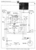
Here's a releasable updated version of the wiring diagram, now showing that the switch poles in the keyswitch are ganged:
6VBenelliWiring2.PNG
And here's the revised regulator simulation:
6VregMk2.PNG
Circuit operation:
If the ignition switch is off, PFETs M1 and M3 are off and isolate both the charging-indicator lamp and the battery from the rest of the regulator.
If the ignition switch is on, the B+ voltage turns on Q1 and hence M1, enabling charging-indicator current to flow to D+. R8 pulls up the gate of NFET M2, switching on field-winding current. As the generator gets up to speed D+ rises, so that charging-indicator current reduces.
Comparator U1a compares a voltage-divided version of the D+ voltage with a 2.5V reference provided by U2. When D+ > 7.2V (as set by Trim1), U1a output goes low and switches off M2 and hence the field current. That current doesn't drop instantly but decays, due to the inductance of the field winding. The decaying field current means D+ decays too, until U1a output goes high again and switches M2 back on. This on/off/on cycle repeats rapidly, stabilising D+ close to 7.2V.
Voltage-divided versions of B+ and D+ are compared by U1c. (Voltage division is used because many comparators don't have a common-mode input range which is rail-to-rail). As soon as D+ > B+, U1c output goes high (pulled up by R17), turning on Q2 and M3, thus allowing current flow from D+ to B+.
U1b compares voltage-divided versions of the voltages at the two ends of current-sense resistor R11. If the current exceeds a limit set by Trim2, U1b output goes low, switching off M2, Q2, and M3. The field current reduces, hence the current through R11 does too. U1b output then goes high again, switching on M2, Q2, M3. This on/off/on cycle likewise repeats rapidly, holding the current from the generator below a desired limit.
R1 and D1 are the (optional) current limiter for the battery. R1 limits the battery-charging current and results in that current reducing as the B+ voltage nears the D+ voltage. D1 is a Schottky diode with a low voltage drop to bypass R1 when the battery is discharging. R1 and D1 each dissipate about 3W (respectively during charging and discharging of the battery). If chassis-mountable versions are used they could be fixed to a metal plate acting as heatsink and housed within the headlight bucket.
R11 and D3 each dissipate ~600mW-750mW. A wide circuit-board track would heatsink R11. M3 could be mounted via an insulator on the wall of a metal enclosure for the regulator.
 

Attachments

  • 6Vreg7.asc
    9.7 KB · Views: 316
Status
Not open for further replies.

Latest threads

New Articles From Microcontroller Tips

Back
Top