Continue to Site

Welcome to our site!

Electro Tech is an online community (with over 170,000 members) who enjoy talking about and building electronic circuits, projects and gadgets. To participate you need to register. Registration is free. Click here to register now.

  • Welcome to our site! Electro Tech is an online community (with over 170,000 members) who enjoy talking about and building electronic circuits, projects and gadgets. To participate you need to register. Registration is free. Click here to register now.

6v Regulator for a Generator System

Status
Not open for further replies.

sign216

Member
I'd like a schematic for a 6V voltage regulator, on an 1969 Benelli (Riverside) motorcycle with a 60 watt 6v generator (DC output, not rectified AC). This is to replace the aging mechanical regulator.

The generator appears to have four stationary coils and a rotating iron/wire commutator. 6v battery with a 9 amp capacity.

It has a Bosch electrical system with a mechanical regulator. The mechanical regulator also protects from too high a current, and from the battery draining out to the system when the engine is off.

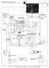
Here is a description of the mechanical regulator: "When the generator voltage is low, current flows through the field windings to ground. This increases the produced voltage. When voltage rises above 7.5, current passes through a resistor to limit the rise. If it continues to rise, the voltage coil shunts the field winding, which prevents if from flowing current. Voltage flow drops to zero then.
The current coil of the regulator measures current from the generator, and drops it if the current rises too much.
The regulator also has a circuit breaker, which is normally open until generator voltage rises above 6.5v, when it closes and opens a path from the generator to the battery, lights, etc.
When the voltage drops, the current coil opens, to prevent the battery from draining to empty via the generator."

Can you guys produce a schematic to replace the old Bosch mechanical regulator? I've scoured the internet and haven't found any diagrams.

Joe
 

I guess you didn't look at the search results before posting.

I don't need pictures of a mechanical regulator. I'm looking to build an electronic regulator to replace the mechanical regulator.
The image search did pull up two electronic schematics, but they were both for regulators for AC alternators, instead of DC generators.

Historically generators and alternators had regulators that worked differently. Generator regulators would provide feedback to the generator, to reduce voltage. What do people think of plopping a modern alternator-style regulator on the line? I guess this would eliminate the feedback to the generator and merely shunt excess voltage to ground, but I don't know anything. It might work ok.
 
Voltage flow drops to zero
Eh? It's current that flows, not voltage. I'm struggling to understand the operation of the regulator from its description.
Does your bike have a negative ground or a positive ground?
 
It is negative ground. I think only the British bikes did positive ground. Attached is a wire diagram, if that helps.
I agree, understanding the operation of the Bosch mechanical voltage regulator is difficult (at least for me).
 

Attachments

  • Wire Diagram.jpg
    Wire Diagram.jpg
    245.2 KB · Views: 1,168
I guess you didn't look at the search results before posting.

I don't need pictures of a mechanical regulator. I'm looking to build an electronic regulator to replace the mechanical regulator.
The image search did pull up two electronic schematics, but they were both for regulators for AC alternators, instead of DC generators.

Historically generators and alternators had regulators that worked differently. Generator regulators would provide feedback to the generator, to reduce voltage. What do people think of plopping a modern alternator-style regulator on the line? I guess this would eliminate the feedback to the generator and merely shunt excess voltage to ground, but I don't know anything. It might work ok.

One just has to know the keywords
http://www.google.ca/search?client=firefox-a&rls=org.mozilla:en-US:eek:fficial&channel=rcs&biw=1384&bih=882&tbm=isch&sa=1&q=mechanical+regulator+replacement+electronic+schematic+dc+generator&oq=mechanical+regulator+replacement+electronic+schematic+dc+generator&gs_l=img.3...29290.33913.0.34741.13.13.0.0.0.0.162.965.9j2.11.0....0...1c.1.64.img..13.0.0.nqvGDLy-ZNo#imgrc=WDiCr4tCP8JvFM:

http://www.next.gr/uploads/135-11129.png
R10 controls the voltage setpoint.
 
Tony, It's great to have you respond. If I need a new search engine, I'll be sure to look you up.
 
dont count on it
 
Although the reg in Tony's second link provides voltage regulation, be aware that it doesn't provide current overload protection so doesn't wholly duplicate the mechanical regulator functions.
 
That looks a better bet, but would need to be adapted for a 6V system.
The field winding has one end (marked Df in the post #5 wiring diagram) which goes to the F terminal of the mechanical regulator. Can you confirm if the other end of the field winding is hard-wired to the D+ terminal or to the Gnd terminal/frame of your generator?
 
Last edited:
Resistance meter confirms that the D+ terminal is grounded.

To help explain the wire diagram, the "emergency battery bypass switch" that D+ and Df go to, is a feature that can start the bike with a dead battery.
Ignition is normally coil + battery. With a dead battery, engage switch, and the bike can be push started. My guess is that then it uses the generator for current to the ignition coil, and bypasses the regulator (but I'm not sure).

Attached is the wire diagram.
 

Attachments

  • Wire Diagram.jpg
    Wire Diagram.jpg
    245.2 KB · Views: 589
Resistance meter confirms that the D+ terminal is grounded.
Eh? That means you have a +ve ground, contrary to what you said in post #5. There should be a few Ohms between D+ and ground for a -ve ground system. But I was asking about the field winding connection.
 
Hi Alec,
The diagram in post #13 only shows two wires from the dynamo. I suspect that there should be a connection to ground on the dynamo that is not show. I suspect that one end of the field winding and one brush is connected to ground. I think the wire labelled D+ is the other brush and the wire labelled Df is the other end of the field winding. I think the OP is confused by a low reading from D+ to ground. I would expect it to be much less than an ohm. (If it was one ohm then there would be 36 watts dissipated in the winding resistance at the full output of 6 amps.)

Les.
 
I misspoke. There's approx. 0.7 ohm between D+ and ground.

This may not be "as designed" since it's 50 yrs old, and junctions have suffered.
 
I suspect that one end of the field winding and one brush is connected to ground. I think the wire labelled D+ is the other brush and the wire labelled Df is the other end of the field winding.
That would be my guess. However, page 11 of the BMW article in the post #6 link clearly shows one end of the field winding connected directly to D+ and no field connection to ground.
6Vreg.PNG
Hence the reason for my question. We need to know which way the field winding connects before we can choose/design an electronic regulator.
 
I agree with Alec. I think the only way to be certain about how it is connected is to remove the end (Brush end.) from the dynamo and examine the connections. I also think the picture at the top of page 12 has the voltage and current coils labelled the wrong way round.

Les.
 
Aargh. The dynamo is housed under the mechanical ignition advance unit, and under the points plate. Tonight (Boston, USA time) I'll do the dis-assembly.
Then I'll able to get the readings you need.
If you can think of a way to get the readings without dis-assembly, I am all ears.

Les, you're right, the picture on pg. 12 of the BMW treatise seems reversed. In it's defense, the BMW article wasn't professionally done. It's merely a shared paper by amateur riders attempting to understand the electrical system.
 
Despite the failings of the BMW article, does the Benelli wire diagram provide the answers?
 

Attachments

  • Wire Diagram.jpg
    Wire Diagram.jpg
    245.2 KB · Views: 511
Status
Not open for further replies.

Latest threads

New Articles From Microcontroller Tips

Back
Top