Continue to Site

Welcome to our site!

Electro Tech is an online community (with over 170,000 members) who enjoy talking about and building electronic circuits, projects and gadgets. To participate you need to register. Registration is free. Click here to register now.

  • Welcome to our site! Electro Tech is an online community (with over 170,000 members) who enjoy talking about and building electronic circuits, projects and gadgets. To participate you need to register. Registration is free. Click here to register now.

68 uF caps installation (9pcs) - current injection necessary?

Status
Not open for further replies.

gubavac111

New Member
I need to replace 9pcs of 68uF caps - https://www.ebay.com/itm/202885535604.

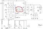
These caps are part of Sine wave filter for the Variable Frequency Drive that is running a big motor on the ship (drawing attached; note that drawing shows only 3 caps, but in reality it is 3 caps between each phases, so 9 in total).


My question is - is it necessary to perform a sort of "current injection" into these capacitors before applying operating voltage?


This procedure is supposed to reduce inrush current once the operating voltage is applied.
I've heard about this procedure from my colleague, but couldn't find any info on it online.


This procedure is supposed to reduce inrush current once the operating voltage is applied and prevent caps from getting damaged, if this makes any sense.


My opinion is this is not necessary because we already had a situation where the system was off for awhile and caps were completely discharged and, once the voltage was applied, it was all ok.


Any opinions?
 

Attachments

  • Capture.JPG
    Capture.JPG
    163.1 KB · Views: 118
I've never heard of any such thing, the only vaguely similar thing I've heard of is reforming old electrolytic capacitors if they haven't been used for an extended period (20-30 years?).
 
I agree with the others.
No precondition needed for dry caps although testing with an RLC meter as well as leakage current at 600Vdc is a quality assurance test. These caps are also used as DeFibrillators so be cautious with memory voltage so discharge pins or avoid contact.

These PolyEthylene film or PE caps are favoured for use as Motor Start/Run caps for all applications for low cost. They are dry film and do not require pre-conditioning.

These are used here as Delta-connected with chokes to act as Sine filters to reduce switching noise from the AFE getting back onto the 3ph grid..

It appears they were made by Roderstein In CK who were bought out by Vishay and list over $200 with PolyPropylene PP caps which Mouser defined as equivalent list at $152 ar RS from BC Components.


here are specs from a different PP cap
1678197159829.png
 
Last edited:
"to reduce inrush current once the operating voltage is applied." would mean degrading the ESR and increasing self-heating and maybe a shorter life. This would contradict the purpose of the caps to provide low ESR. Although there must be some ESR in the chokes to dampen the AFE rectifier currents without excessive resonance sqrt(L/C)/ ESR = Q while the chokes are better suited to dissipate heat than these C "insulators".

This raises my curiosity. Did your colleague once perform this test on the caps to be replaced? How long did they operate?

I apologize - which test are you talking about exactly? These caps have been in operation between 7 and 9 years.
 
As the others say, they should be fine. They are intended for high current and pulse applications, and in your application there are inductors at both the supply and load sides which will limit the rate of rise when the supply is switched on.

I can't find data on the 750V version, but the 900V 68uF in that same range is rated at 80A operating current and 300V/uS pulse.

Check for unreasonable leakage at eg. 500V with a megger before installing them, just to be safe, in case any have been damaged in storage - but other than that, just use them.

This is the closest datasheet I could find, for reference:
 
I apologize - which test are you talking about exactly? These caps have been in operation between 7 and 9 years.
"a sort of "current injection test" is not necessary. The quality tests are recommended.
 
I've heard about this procedure from my colleague, but couldn't find any info on it online.
I suspect that the Dunning-Kruger Effect is in operation here.

Over the years it has been my experience that someone will insist that something must be done a certain way, when the truth is that they just talking rubbish.
They have been told something, or read something which they partially understand and are now mis-applying that "knowledge" in a most inappropriate way.

JimB
I would agree, it's just a myth passed on by someone who doesn't know what they are on about.
 
Considerations for C inrush current reliability :


During the “current spike”, high current is flowing through the lowest impedance parts of the capacitor and as this a “high frequency” ripple load type, the current path will flow first mainly through a “surface skin effect“ area of conductive materials. The capacitor dielectric may be then subjected to immediate high electrostatic mechanical pressure force once the electric field on electrodes is created. Depending on duration of the surge spike, Joule heat is generated that has to be absorbed by the capacitor. This is indeed more relevant to the dI/dt transient discussed in the next chapter, but the initial spike may generate some “pre-conditioning” stage of the capacitor and a total energy to be dissipated by the capacitor during the power on sequence has to be considered.

Other considerations for film caps :


Regards, Dana.
 
Last edited:
Status
Not open for further replies.

Latest threads

New Articles From Microcontroller Tips

Back
Top