Continue to Site

Welcome to our site!

Electro Tech is an online community (with over 170,000 members) who enjoy talking about and building electronic circuits, projects and gadgets. To participate you need to register. Registration is free. Click here to register now.

  • Welcome to our site! Electro Tech is an online community (with over 170,000 members) who enjoy talking about and building electronic circuits, projects and gadgets. To participate you need to register. Registration is free. Click here to register now.

5x7 Matrix Issue

Status
Not open for further replies.
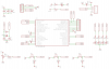
Thanks Beebop... Im looking at the PICDEM FS USB User Guide at the schematic. Im wondering what they use that mosfet for. Looks like it blocks the VBUS (+) from the rest of the circuit if the user supplies power via adapter. Would that be correct?

Sound correct to me. With no voltage at pin 3 of the regulator, the gate is pulled down to ground by R22. When the user plugs in an adapter there is a positive potential on the gate which shuts down the fet. Quite an idea; I'll have to remember that one.:D
 
I bought one of **broken link removed**. It's fully TI compatible so it works with their software. TI's JTAG uses a 2x7 header.

I also have a **broken link removed** Spy Bi-Wire unit.


They're designed to run at ultra low power levels and just blip up to high speed in short bursts when needed.

Sweet!:D I'm surprised you didn't get them over at SparkFun. Ah, it's a canuck site; going to have to have a look around that one. Thanks.:D

I'm going to have to watch your progress on this one!:)
 
My version of that PICDEM FS USB board. Less Parts. Full PORTB output for use with w/e. Fully usb powered (or ICSP powered).Should be smaller and will make it have like a small expansion port. like 6-10pin for various addons. For testing. Mainly for me but since im posting the schematic feel free to use it for w/e. Im making this mainly to be a cheaper solution to the original microchip PICDEM FS USB.

Original $60

Mines would cost maybe $20 (max) to make Once you figure in the PCB Creation. The most expensive part would be the PCB & the PIC itself :)
 

Attachments

  • picdemusb2.png
    picdemusb2.png
    47.3 KB · Views: 124
Last edited:
Just a suggestion, but if your including the programming header, AND allowing full access to port B, I think you should include the protection circuit (from the datasheets) that prevent the external circuit from interfereing with the programming and vice versa.

It wouldnt matter on a normal circuit, but on a board designed to be 'played' with - I would highly recommend this.
 
I shift over from datasheet pdfs to tips & tricks pdfs to manual and am always changing add/removing items. Thank you for the tip... ill be sure to add that in.
 
Status
Not open for further replies.

Latest threads

New Articles From Microcontroller Tips

Back
Top