Continue to Site

Welcome to our site!

Electro Tech is an online community (with over 170,000 members) who enjoy talking about and building electronic circuits, projects and gadgets. To participate you need to register. Registration is free. Click here to register now.

  • Welcome to our site! Electro Tech is an online community (with over 170,000 members) who enjoy talking about and building electronic circuits, projects and gadgets. To participate you need to register. Registration is free. Click here to register now.

5x7 Matrix Issue

Status
Not open for further replies.
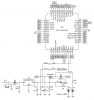
My SD socket doesn't yet have the four mounting pads/shell automatically connected to ground yet. I'm still learning about how to do that. I'll repost when it's done. If you use it before I repost, fix that.


I do now! :D

Oh, no worries, I learned - the hard way :p - to always check first.:D
 
Which SD socket did you buy, I've got to use one in an upcoming project
Digikey 3M5607CT-ND. It's a micro, so if you need a full or mid size SD socket buy something else.

and am baffled by the sheer amount of different SD sockets there are.
Haha. Ya, everyone makes one, or several or dozens of types.

I plan on using a MAX3392E level converter for the 5V to 3.3V level translation.
I'm putting my first one on a new TI MSP430F157 board I'm designing, so no level conversion necessary. They're all low voltage MCUs.
bleh.png
 
Last edited:
Futz, nice board. Why don't you get rid of more of the square corners, though?

How to make a custom library part in Eagle CAD tool

is NICE! Ill make PDF and save!

I actually learned all i know from
**broken link removed**

FUTZ:
Nice work as usual. I see you are still on the TI stuff. Hows it treating you? Is it living up to your expectations?

That seems like a big job, but I know why you might do this; too many good things on the net disappear, and I like to have the info local. Perhaps if you do get a PDF together you will put it up here.

Thanks AtomSoft, that Eagle Editor Tutorial looks pretty good. Wish I'd had that way back when. I'm still going to enjoy reading through as there may be something left to learn.:D
 
Futz, nice board. Why don't you get rid of more of the square corners, though?
I think it is still a Work In Progress. I can see 7 via's right off the bat that could be eliminated (From the center header on the lower edge of the PCB). Autorouter madness! :D
Nice eagle links. Thanks!
 
I think it is still a Work In Progress. I can see 7 via's right off the bat that could be eliminated (From the center header on the lower edge of the PCB). Autorouter madness! :D
Nice eagle links. Thanks!


Yes, I think you are right about that. I used to let the autorouter suggest, but these days I just avoid it.:p

IIRC those links came from SparkFun...
 
on the topic of eagle... When making a schematic how the hell do you make it like wireless on the schem?

Ok i know that was confusing. ill try to explain. Look at almost any schematic they have a tag on the pins like VDD might have a line to a <5v> type tag and then that tag it also on anything that needs the <5v> so anything that has a 5v tag is connected. You understand?

Look at bills page: https://www.blueroomelectronics.com/

see the junebug underneath it is a schematic. See the PGC and PGD and stuff under the right wheel in the picture. How do i make those in eagle?
 
Last edited:
on the topic of eagle... When making a schematic how the hell do you make it like wireless on the schem?

Ok i know that was confusing. ill try to explain. Look at almost any schematic they have a tag on the pins like VDD might have a line to a <5v> type tag and then that tag it also on anything that needs the <5v> so anything that has a 5v tag is connected. You understand?

Um, do you mean naming the nets the same as other nets, and they get connected automatically? Like a bus?
 
Yeah BeeBop... but it would be nice to have that little thing like a label part. Now with a N-Channel...

nmosfet-png.23706
 

Attachments

  • nMosfet.png
    nMosfet.png
    2.8 KB · Views: 266
  • AtomSoft.zip
    3.2 KB · Views: 92
Last edited:
I think it is still a Work In Progress. I can see 7 via's right off the bat that could be eliminated (From the center header on the lower edge of the PCB). Autorouter madness! :D
That was just a quick autorouter-only test. The board is far from finished. :p As I do it I'm relearning all the stuff I used to know how to do in Eagle years ago but forgot. Still a ways to go...
 
I actually learned all i know from
**broken link removed**
Here's a few more:
gaussmarkov: diy fx » Eagle 2: Libraries
ECE101 - Basic Electrical and Computer Engineering » Blog Archive » EAGLE Implicit Pins - Addlevel Explanation
**broken link removed**

I see you are still on the TI stuff. Hows it treating you? Is it living up to your expectations?
I still say, "Nice MCUs!". You can run em off fruit! :D I don't care much for their IDE, but I can live with it. MPLAB sets a pretty high bar for MCU IDE's.
 
awesome links thanks and cool fruit stuff. I doubt if we had to run it off fruit it would be very usefull :) maybe a watch? but then you lose time in between fruit :D but thats cool!
 
Found it Beebop

Under Supply 2:
V-->
V<--

COOL!
:p:p:p
God, I'm getting old! I didn't get what you were saying.:D

Difference between a MOSFET and bipolar transistor? In a 'nutshell,' the transistor is controlled by current - more current on the base turns it on harder, up to the point it saturates. The FET is controlled by voltage. There are two basic kinds - depletion mode and enhancement mode. With the depletion mode a voltage on the gate which is more negative with respect to source, chokes off the device so it doesn't conduct from drain to source. Enhancement mode FETs need a voltage on the gate to turn them on. IIRC

I still say, "Nice MCUs!". You can run em off fruit! :D I don't care much for their IDE, but I can live with it. MPLAB sets a pretty high bar for MCU IDE's.
I've heard tons of good things about the MSP micros. How will you burn the firmware into the chip?
 
Last edited:
Thanks Beebop... Im looking at the PICDEM FS USB User Guide at the schematic. Im wondering what they use that mosfet for. Looks like it blocks the VBUS (+) from the rest of the circuit if the user supplies power via adapter. Would that be correct?

schemfs-png.23711
 

Attachments

  • schemfs.png
    schemfs.png
    67.6 KB · Views: 265
I've heard tons of good things about the MSP micros. How will you burn the firmware into the chip?
I bought one of **broken link removed**. It's fully TI compatible so it works with their software. TI's JTAG uses a 2x7 header.

I also have a **broken link removed** Spy Bi-Wire unit.

Ha, I just watched the video. You weren't kidding.
They're designed to run at ultra low power levels and just blip up to high speed in short bursts when needed.
 
Last edited:
Status
Not open for further replies.

Latest threads

New Articles From Microcontroller Tips

Back
Top